 International
 Singapore
 Malaysia
 Thailand
 Vietnam
Your shopping cart is empty!

IRIV PiControl - Controlling a 24V Relay with Push Button
- Abdulrahman Alhamed
- 27 Feb 2024
- Tutorial
- 392
Welcome to our follow-up tutorial on using Node-RED for digital input and output. In this tutorial, we'll be practicing what we learned in our previous tutorial by connecting an external push button to control a 24V relay.
Hardware
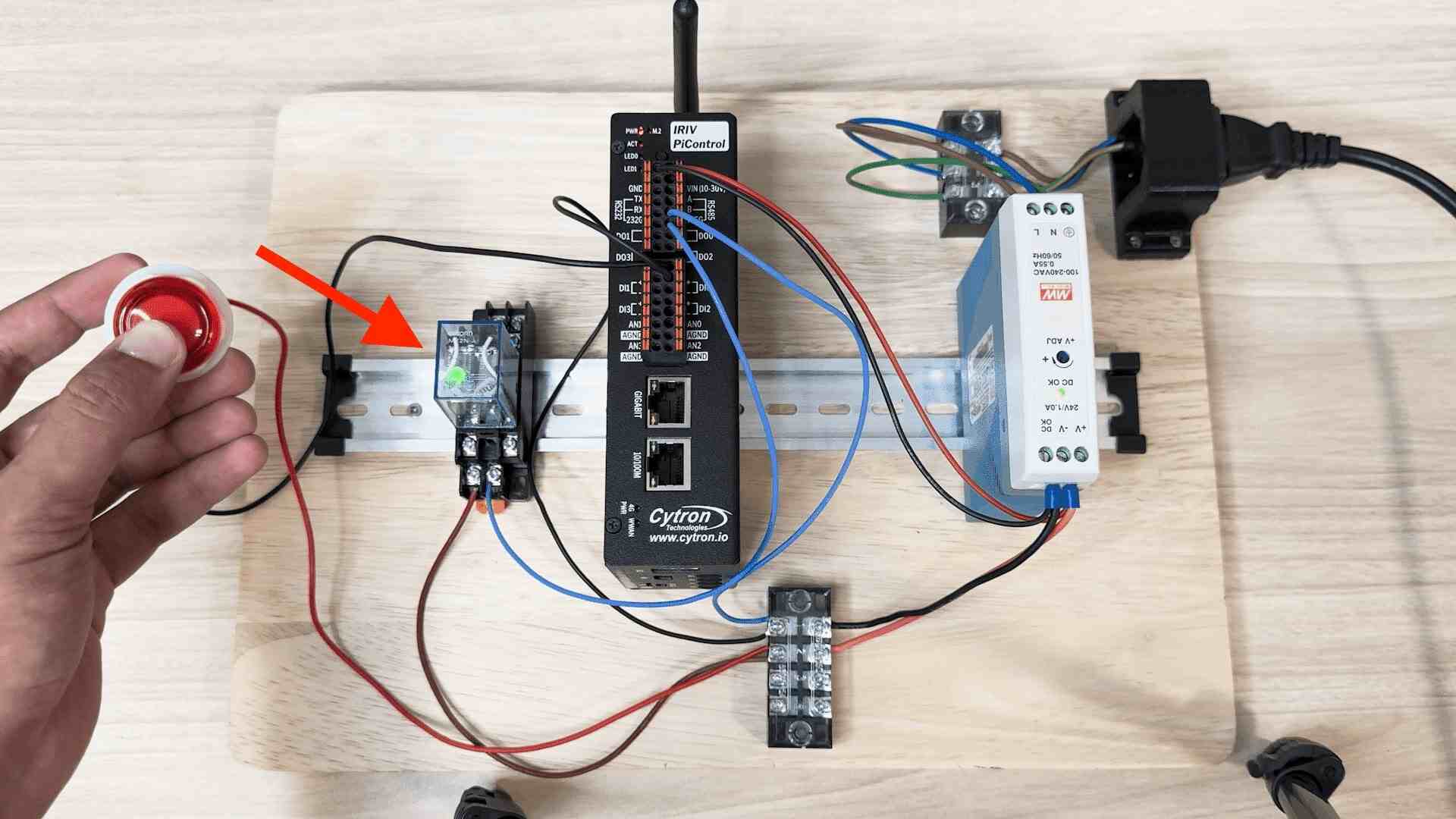
Connection Diagram
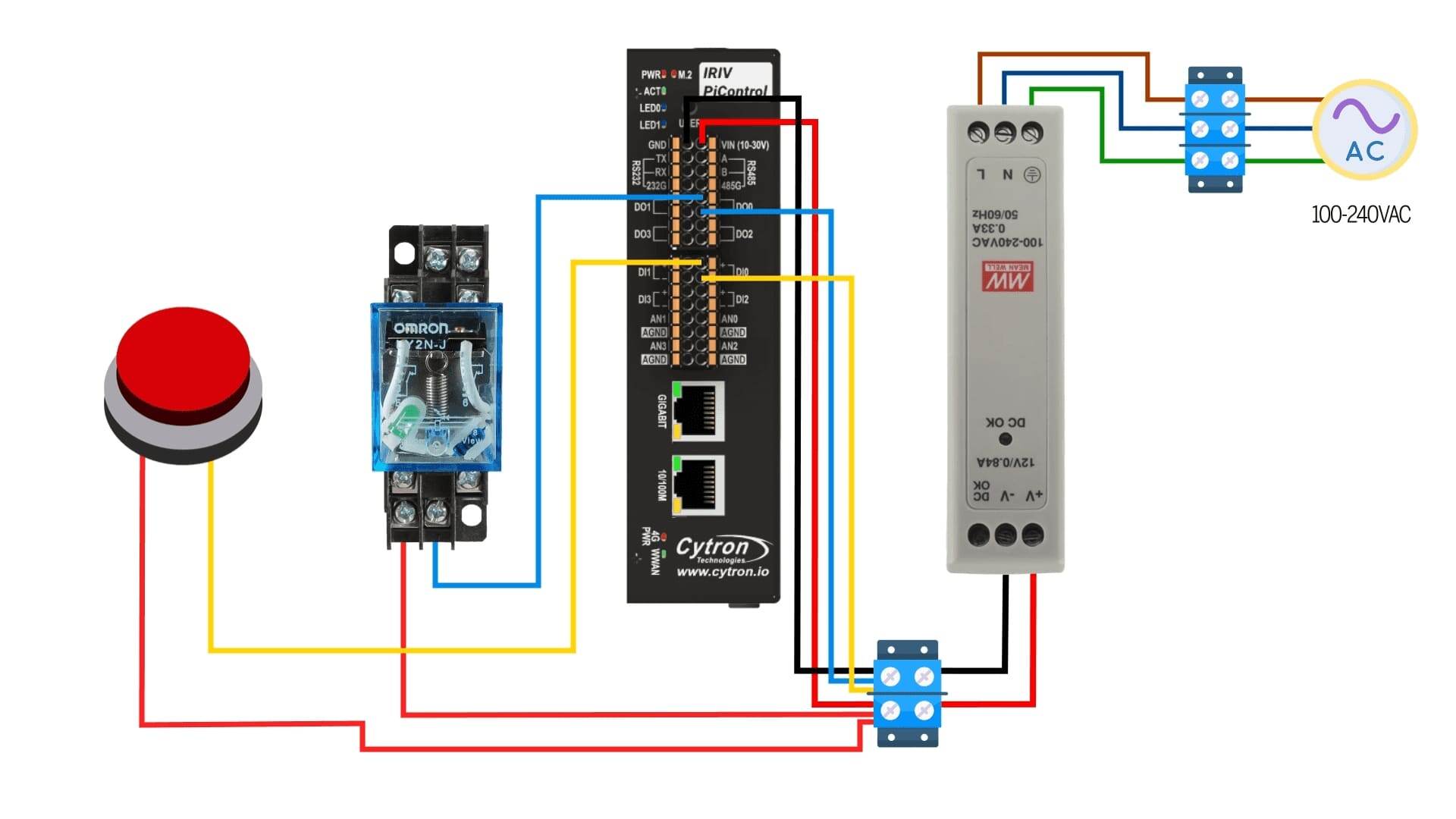
Power Supply Connection:
- Start by powering up the 24V power supply using a 120-240V AC source.
- Connect the power supply to the IRIV PiControl.
Relay Connection:
Since we're working with isolated digital input and output in IRIV, connect the relay as follows:
- Connect one end of the relay to the power supply.
- Connect the other end of the relay to the DO0 (digital output 0) pin on the IRIV PiControl.
- Double-check the polarity to ensure correct connection.
Push Button Connection:
Similar to the relay, connect the push button as follows:
- Connect one end of the push button to the power supply.
- Connect the other end of the push button to the DI0 (digital input 0) pin on the IRIV PiControl.
Note: Please remember to handle all connections with care and double-check connections for accuracy.
Node-RED Programming
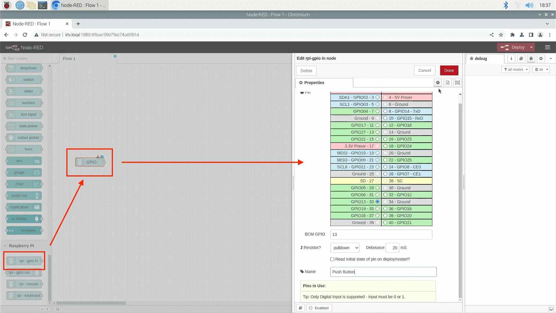
From the palette drag the GPIO-in node to the workspace, open the configuration window, and select GPIO 13, as it is the Digital Input 0 in IRIV, you can refer to the datasheet for more info. Change the resistor to pull-down, and name it Push Button.
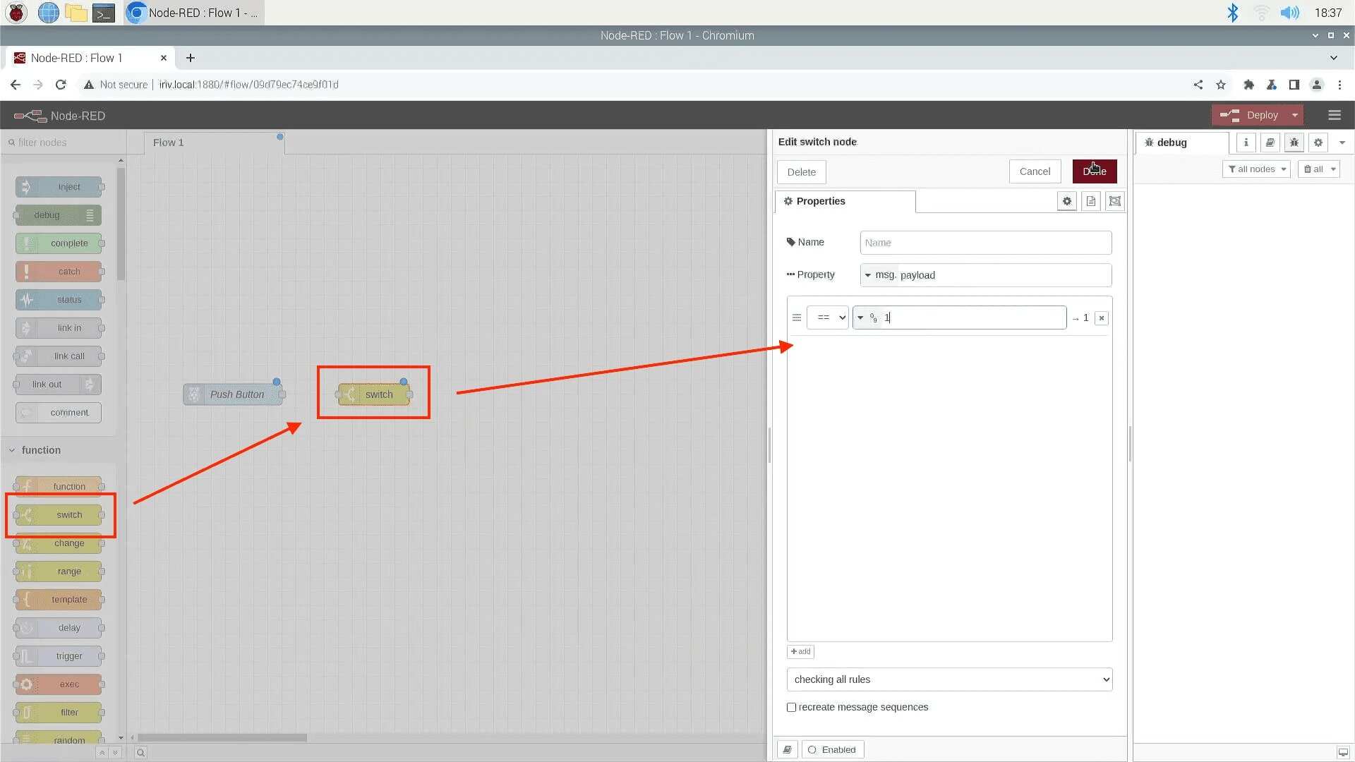
Then drag a switch node, open it, and let's test for number 1, which means it only gets activated once we press the button.
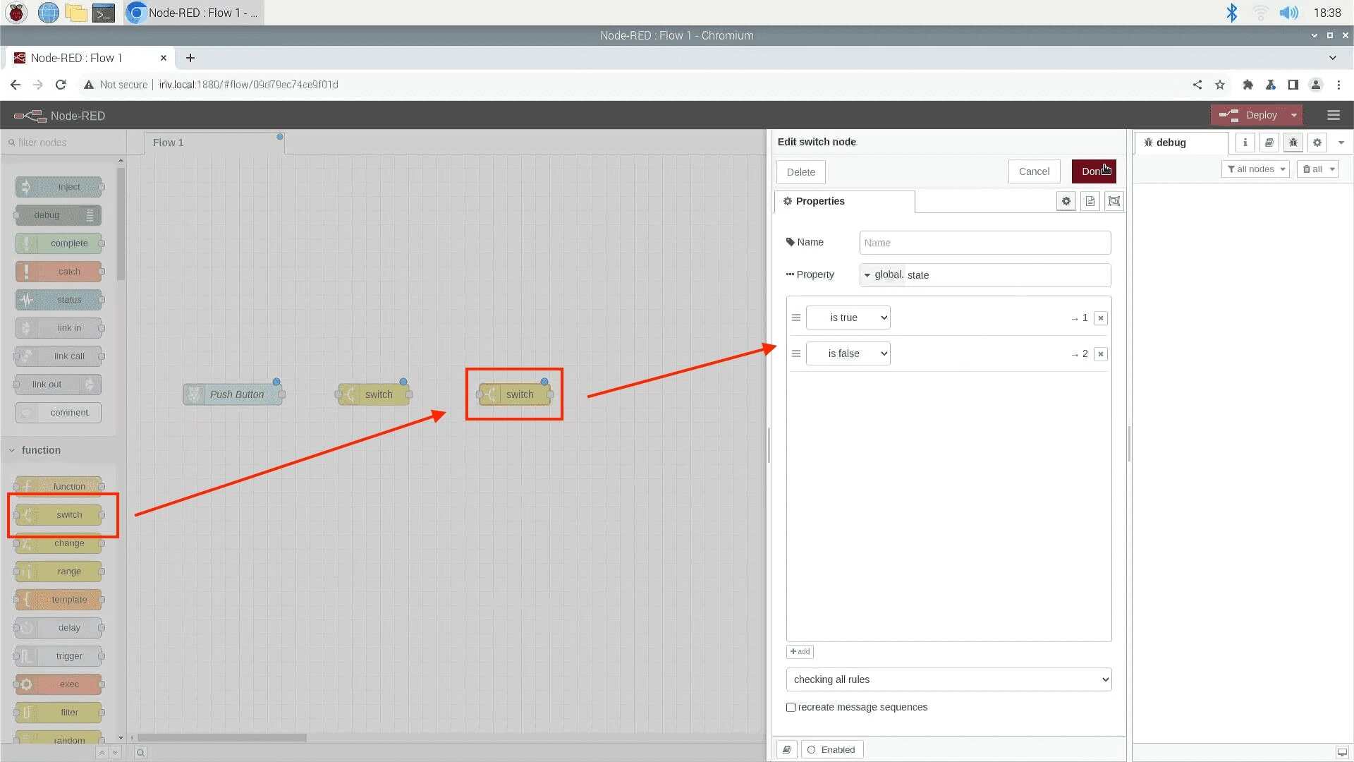
now, add another switch node, the purpose of this node is to look at the state of the push button, if it is true we will go one path, if it's not we will go another path. change the property to (global. state), and check for 2 possible values, first one is true, and the second one is false.
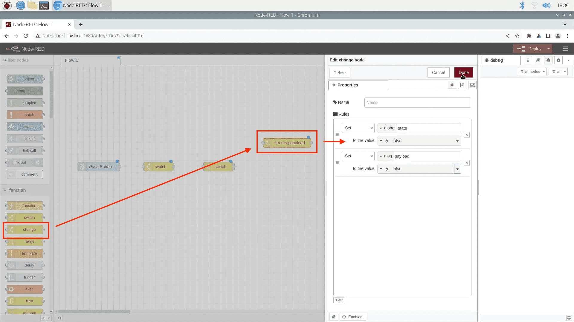
now will add 2 change nodes, to change the state from true to false, or from false to true. Open the first change node, set the property to (global. state), and set it to false, and set the (msg. payload) to false as well.
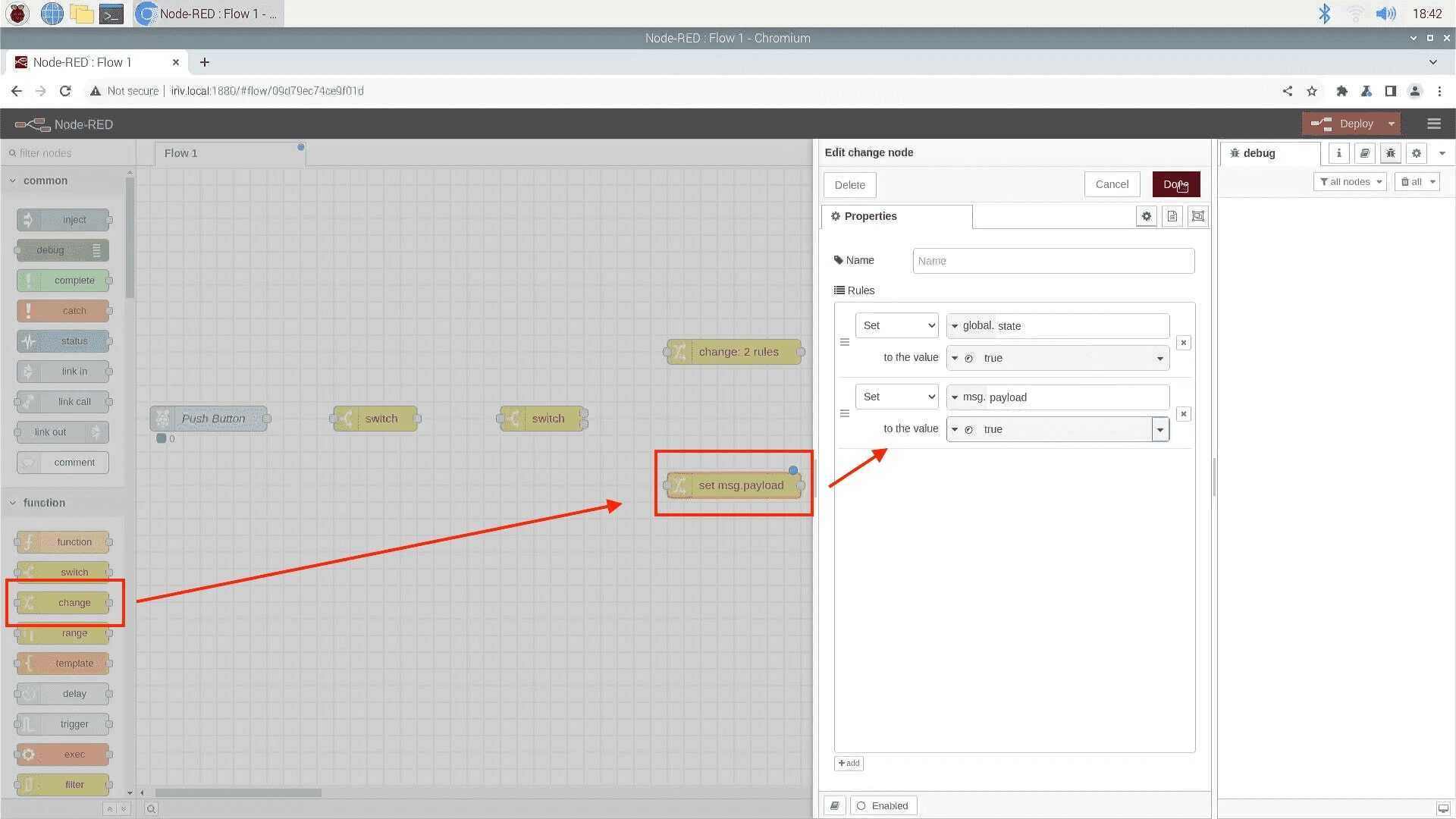
Open the second change node, set the property to (global. state) and set it to true, and set the (msg. payload) to true as well.
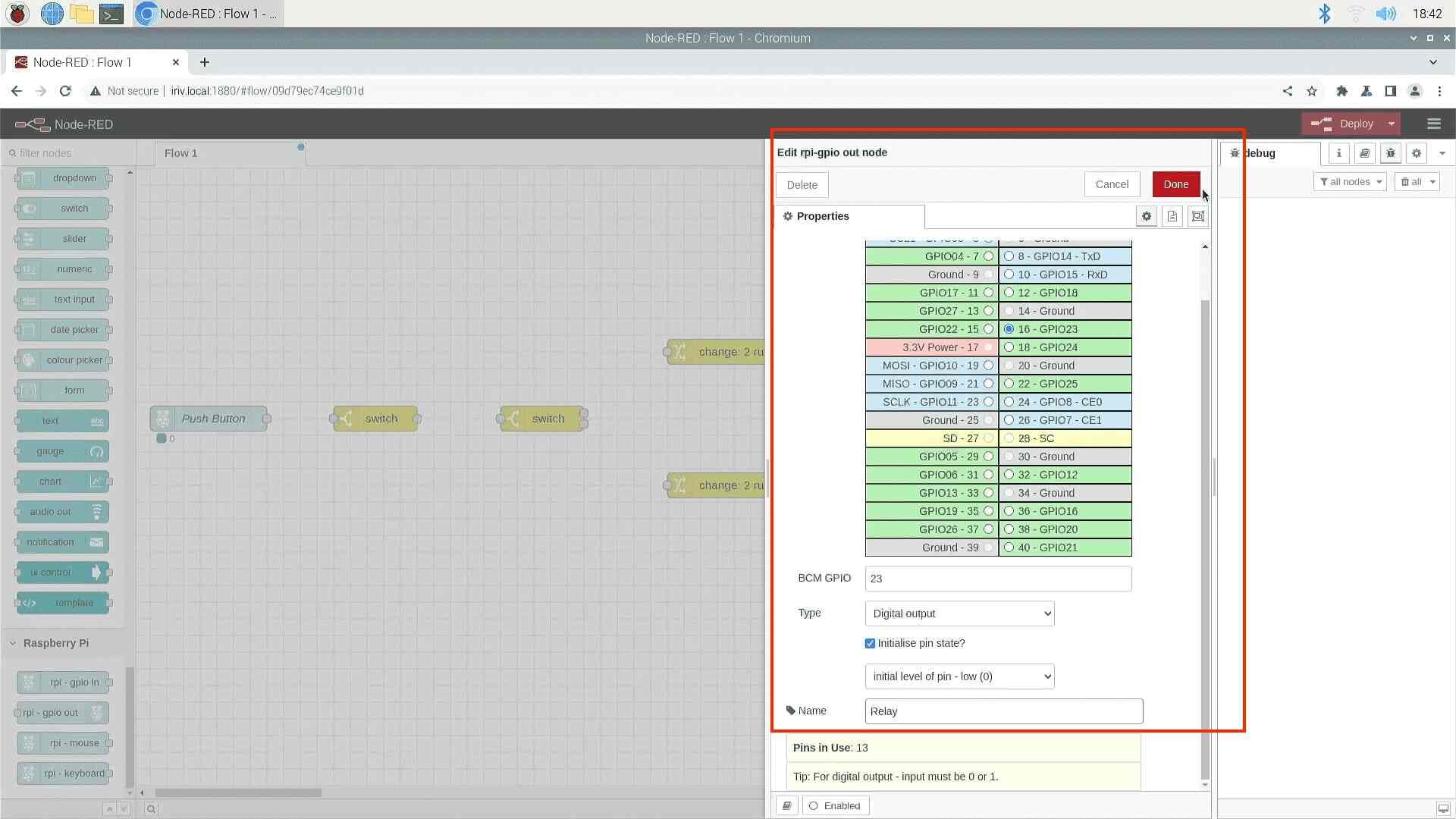
Now drag GPIO-out node, and set it to GPIO23, and name it Relay.
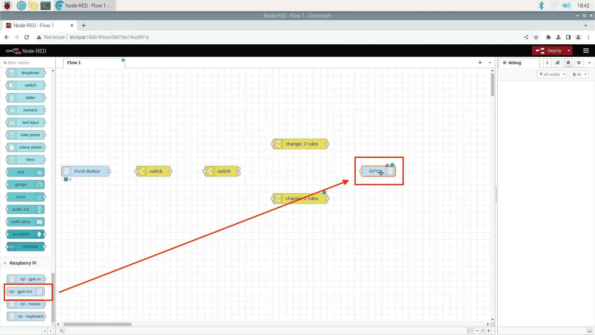
Now connect all the nodes together this way, and hit display to test out our program.
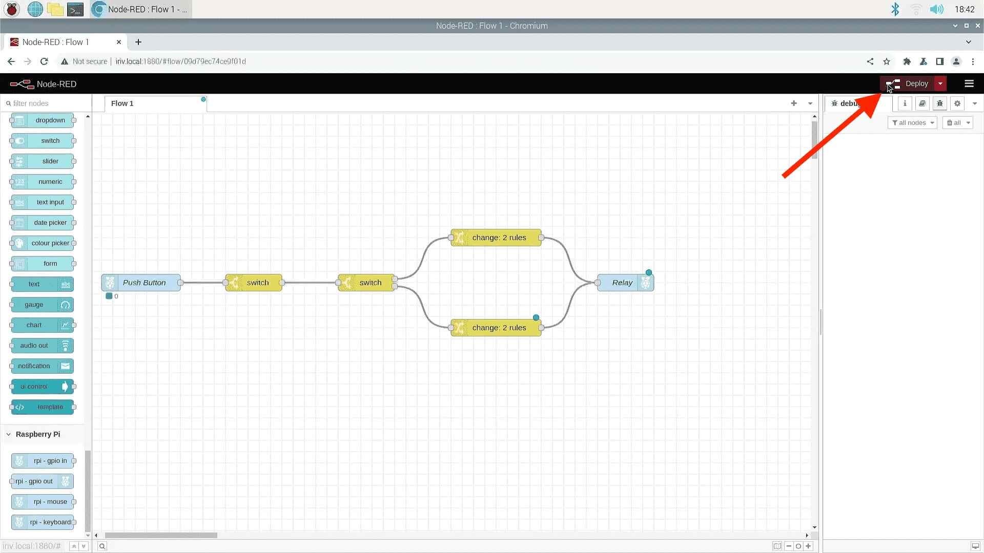
Press the push button to activate/deactivate the relay.
Great! Now you've learned how to use a push button with 24V relay. Stay tuned for more tutorials.
Hardware Components

IRIV PiControl - IR4.0 CM4 Industrial Controller
RM1,345.00++
x 1 unit(s)