 International
 Singapore
 Malaysia
 Thailand
 Vietnam
Your shopping cart is empty!

Build 1KG RC Sumo Robot using MDDRC10
- Khairul_Tajudin
- 01 Feb 2024
- Tutorial
- Beginner
- 624
This tutorial guides you through the creation of a custom RC Sumo Robot based on the MDDRC10 Motor Driver, designed for the 1kg Sumo Robot Competition in the RC category. The robot has dimensions of 15cm (L) x 15cm (W) and a weight below 1kg.
Component list:
1. 10Amp 7V-30V DC Motor Driver for R/C (2 Channels)
2. 12V 980RPM 2.3kgfcm High Power Brushed DC Geared Motor
3. FlySky 6 Channels RC Radio Transmitter with FS-iA6B Receiver - Mode 2
4. LIPO Battery 11.1V 1300mAH or LiPo Rechargeable Battery 11.1V 1500mAh 25C
5. Dean T LiPo Battery Wire Extension 20cm
7. Self Tapping Screw
8. G25T1 Silicone Wheel Set (43mm x 30mm)
[You can download the STL file here - RC SUMO ROBOT 1KG STL]
Step 1: Gather 3D Printing Parts
Start by gathering your 3D printing parts. For basic slicer setup, refer to our Ultimaker Cura Setup.
Slicer Settings:
- Layer Height: 0.2mm (Standard Quality)
- Infill: 20%
- Adhesion: Off
- Support:
- BattCover - no support
- Motor Bracket - no support
- Robot Base v3 (Cut_Portable) - with support (touching buildplate)
- Robot Base v3 (Soccer) - with support (touching buildplate)
- Robot Base v3 (Weapon) - with support (touching buildplate)
- RoofRC - with support (everywhere)
Step 2: Assemble Your Robot
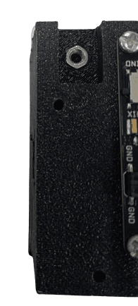
1. Start with the motor bracket part. Insert the M3 nut into the designated slot.
2. Put the motor bracket on robot base
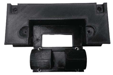
3. Put a M3 bolt to connect motor bracket and robot base. No need to tight the bolt and nut yet. Left it loose until we insert DC Motor on it.
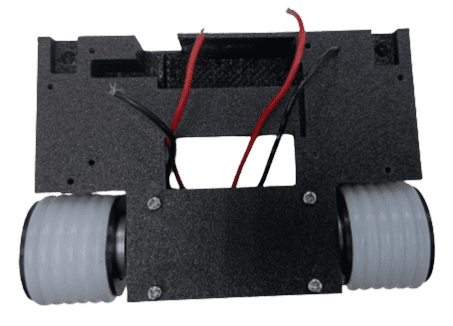
4. Wiring your DC Motor with suitable wire. Suitable length of wire is around 10cm.
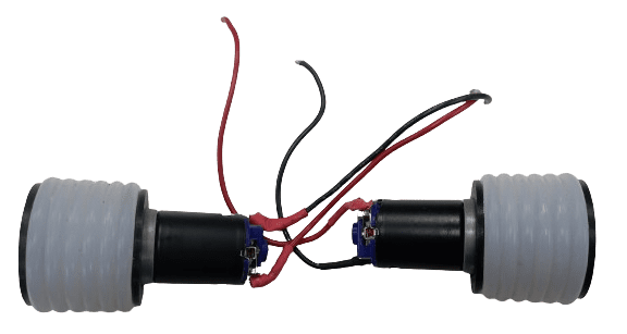
5. Insert your DC Motor inside motor bracket. Set a suitable tolerance between motor bracket and silicon wheel to make sure it have a gap to turn motor later.
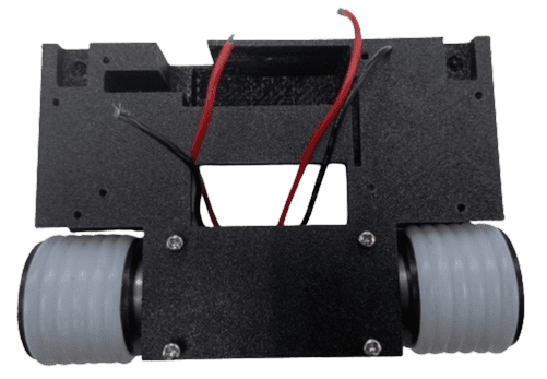
6. Tighten the bolt and nut between motor bracket and robot base. Make sure to make it tight and DC Motor not loose from motor bracket.
7. Bring up the wire. Later we will connect it to our motor driver.
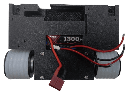
8. Put Lipo Battery 11.1V into the designated slot. Bring the battery connector to another side of robot base.
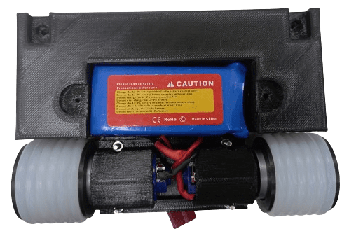
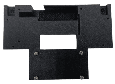
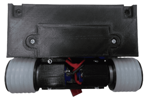
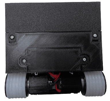
9. Place the battery cover to the slot
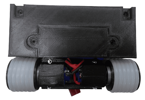
10. Battery cover is actually push fit slot, but if want to secure the cover, you may insert the self tapping screw on it.
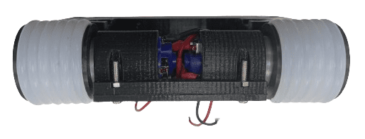
11. Arrange your DC Motor and Battery wire properly. Reserve the space for our MDDRC10 Motor driver.
12. Put your RC Receiver (in our case using FS-iA6B) into the slot that already design for this receiver.
*if you using another type of receiver and not suit the designated placement, you may consider to put the receiver outside this slot.
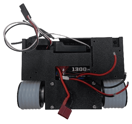
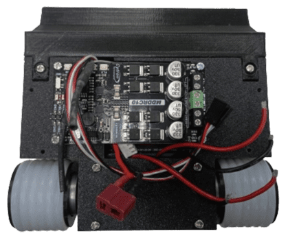
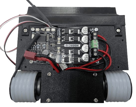
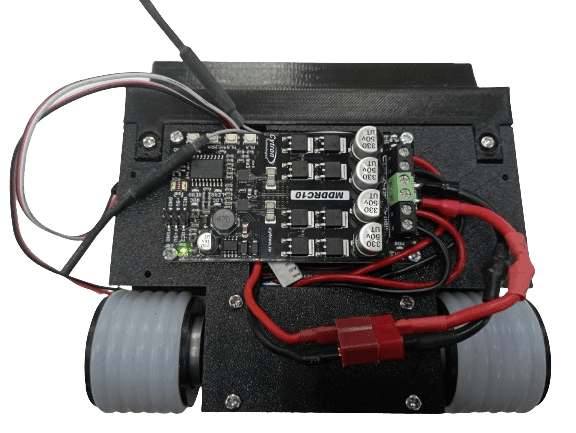
13. Now, its time for our powerful MDDRC10 motor driver. By using self tapping screw, connect the board to the robot base. Arrange carefully your receiver connector wire and antenna.
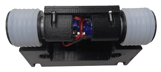
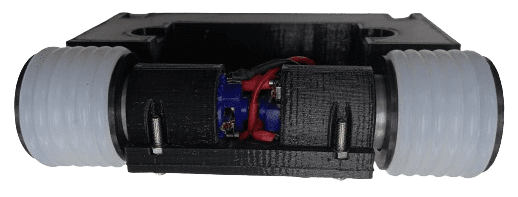
14. Next we will place the weapon to the robot. There are slot to connect the Robot Base (weapon) with Portable Robot base. You may insert the M3 Nut here and glue it. It to make sure it can hold the impact during the our match later.
15. Put also the screw at the bottom of the robot base with the same step as before.
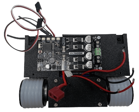
16. Wiring the DC Motor wire into MDDRC10 motor driver. Properly insert the wire into left and right motor slot. No need to consider the color of wire yet, we will adjust it during testing (step 20) to decide the oriention of motor movement.
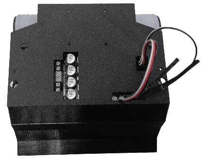
17. Next, we put Lipo Connector into the power slot on motor driver. Please make sure you follow the +ve and -ve port to avoid faulty to the motor driver.
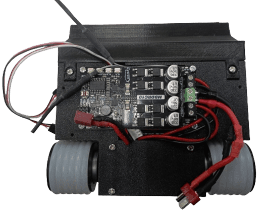
18. After you are confident with your wiring, connect the Lipo battery to the connector to power up the board. This connection is temporary only to test the motor driver board.
19. Press the test button to test the direction of the motor.
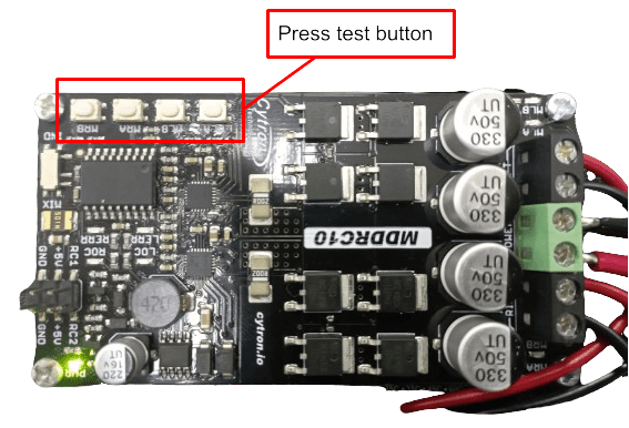
Left Motor
MLA - should move forward (clockwise)
MLB - should move backward (anti-clockwise)
Right Motor
MRA - should move forward (clockwise)
MRB - should move backward (anti-clockwise)
*if you notice, one of the motor move in difference direction, you need to swap the wire in motor driver terminal block port.
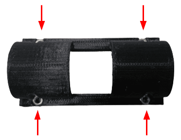
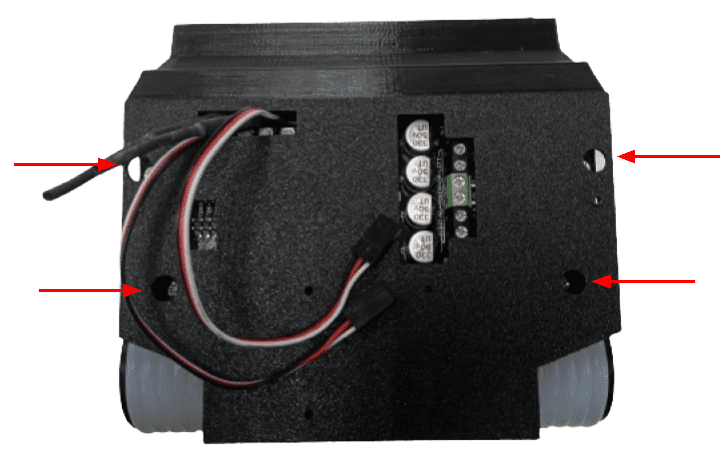
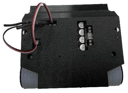
20. Next, we will put the cover the robot. The purpose is to protect the board and wiring during the fight. There are 4 screw to connect the roofRC with the robot base. Make sure to screw all to make it more firm.
21. Connect the receiver wire to the motor driver RC Port.
22. Refer to this diagram for wiring RC Receiver with MDDRC10
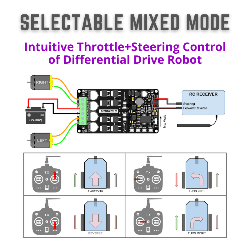
23. Your robot is now ready for battle!
Hardware Components

x 1 unit(s)
")
x 1 unit(s)
 Backorder Only
x 1 unit(s)
Related Posts
