 International
 Singapore
 Malaysia
 Thailand
 Vietnam
Your shopping cart is empty!
-800x800.jpg "Adafruit IS31FL3741 13x9 PWM RGB LED Matrix Driver - STEMMA QT / Qwiic")
-800x800.jpg "Adafruit IS31FL3741 13x9 PWM RGB LED Matrix Driver - STEMMA QT / Qwiic")
-800x800.jpg "Adafruit IS31FL3741 13x9 PWM RGB LED Matrix Driver - STEMMA QT / Qwiic")
-800x800.jpg "Adafruit IS31FL3741 13x9 PWM RGB LED Matrix Driver - STEMMA QT / Qwiic")
Your shopping cart is empty!
Add a splash of RGB LEDs to a project you're working on, with this adorable 13x9 RGB LED matrix breakout. It features -- no surprise -- 117 RGB LEDs, each one 2x2mm in size, in a 13x9 grid with 3mm pitch spacing.
.jpg )
These are not NeoPixel or DotStar or other 'smart' RGB LEDs. Instead of having a lil chip in each LED, there's one large controller chip that handles all the PWM for you. The ISSI IS32FL3741 communicates over I2C and can set each LED element with 8 bit PWM for 24-bit color across the RGB elements, for beautiful color! There's an adjustable current driver so you can brighten or dim the whole display without losing color resolution.
Each assembled board comes with the grid, four mounting holes, and the IS31FL3741 chip with all supporting circuitry. The board can run from 3.3 to 5V DC power and logic - powering from 5V is recommended since the green and blue LEDs look better with the extra headroom. Since its a multiplexed matrix with one cathode on at a time, and each cathode driver can sink about 40mA max, that is the max current draw you can expect from the matrix. We use ultra-bright LEDs so even at ~4mA per multiplexed LED they are nice and bright!
We designed the PCB so you can tile the boards side-to-side if you desire, you'll just have to cut/solder the jumpers on the bottom to change the I2C address: Up to 4 boards can share one I2C bus.
Use Arduino or CircuitPython/Python to quickly set pixels to any color you desire. Note that I2C makes this board very easy to wire up but that also makes the display slower because each pixel must be written over I2C. For a small display with simple animations, its fine - but if you want to do video or larger graphics we recommend upgrading to the HUB75 style.
We made it easy for you to get some color right into your next project. The LED matrix and circuitry is soldered onto a custom-made PCB with two STEMMA QT connectors on the top, and are compatible with the SparkFun Qwiic I2C connectors. This allows you to make solderless connections between your development board and the IS31FL3741 or to chain it with a wide range of other sensors and accessories using a compatible cable.
To know more about STEMMA QT, watch this video:
.jpg )
.jpg )
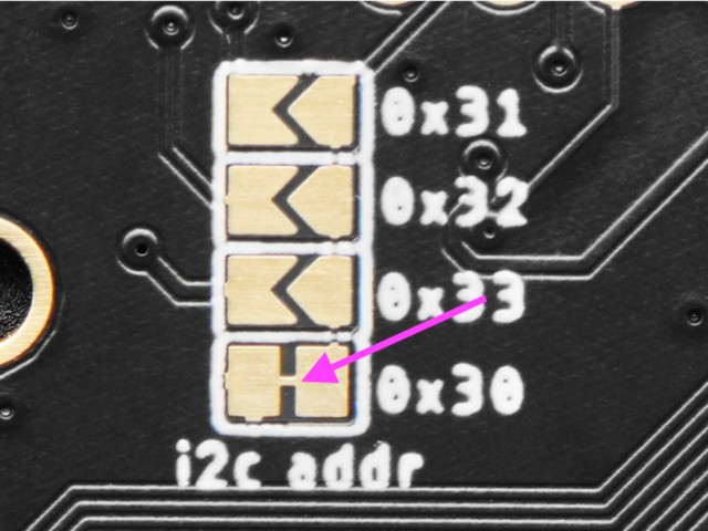
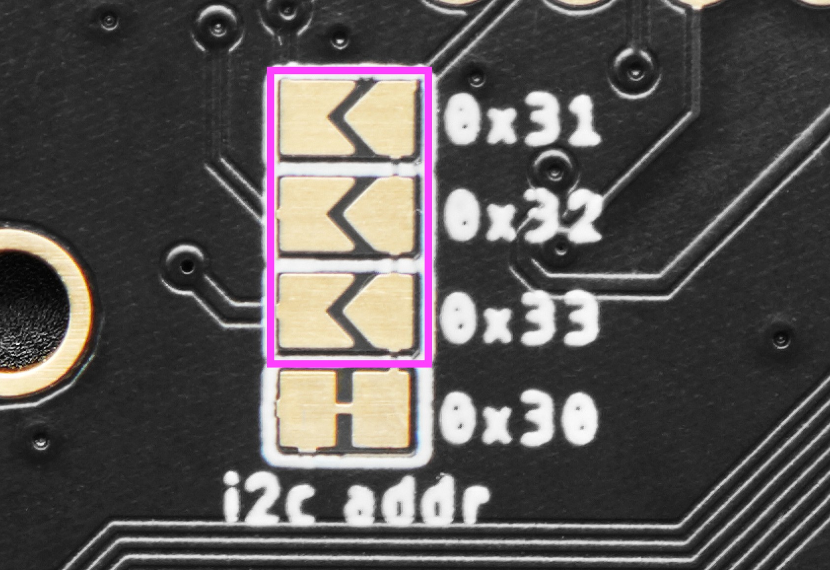
Solder ONE of the other three sets of jumper pads (highlighted in the image) to change the address. Solder only one at a time. The addresses are listed on the back of the board next to each jumper. Here are the details:
.jpg )

