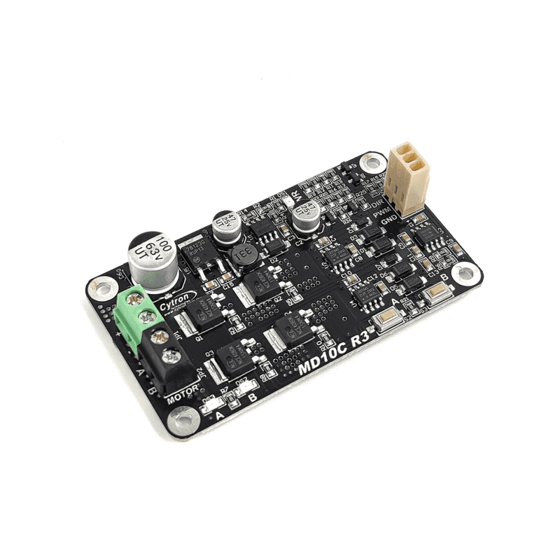
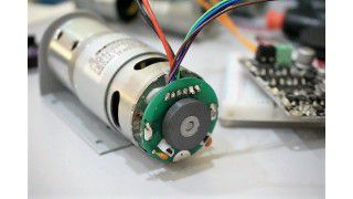
DC brushed motor is the most commonly used and widely available motor in the market. Getting the motor to rotate is fairly easy, just connect the two terminals to power source and it will start spinning, that's the beauty of DC brushed motor. Yet, if you want to control the speed, direction, activation and automate all these functions, check out this tutorial: 5 easiest ways to control a DC motor. And a motor driver is one of the ways. MD10C is one of Cytron's motor driver series which offers easy to use features.
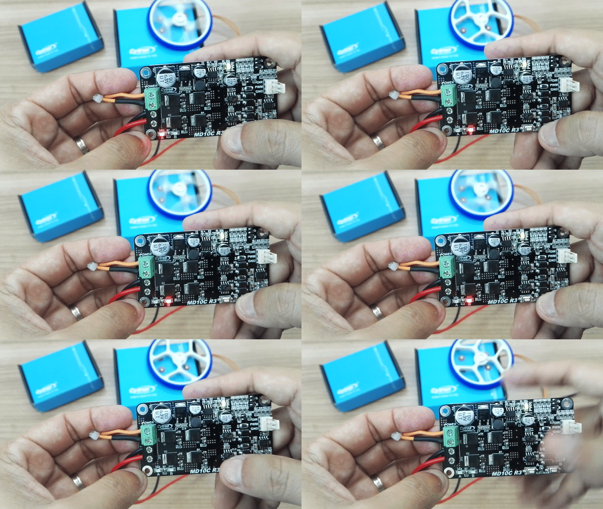
As easy as pressing button, everyone can do it!
*Do check out MD13S which is SMD version of MD10C that have similar spec at lower price! MD10C is a newer version of the MD10B(2008) which is designed to drive high current brushed DC motor up to 13Amps continuously. It offers several enhancements over the MD10B such as support for both locked-antiphase and sign-magnitude PWM signal as well as using full solid state components that result in faster response time and eliminate the wear and tear of the mechanical relay. And with Cytron's motor driver special feature: the on-board manual/test buttons, MD10C is super easy to get started. Check this video to get started without any controller.
Nonetheless, it is compatible with Arduino, even Arduino or Raspberry Pi that generate 3.3V logic PWM. Check this video out:
Which motor is good to be driven by MD10C? As long as the motor:
- DC Brushed motor (Two terminals)
- Operating voltage from 5V to 30V
- Rated Current ≤ 13A
- Peak Current ≤ 30A
Example of suitable DC brush motor with MD10C (Not limit to):
Overview of MD10C
Warranty Period: 12 months
 International
 Singapore
 Malaysia
 Thailand
 Vietnam
