 International
 Singapore
 Malaysia
 Thailand
 Vietnam
Your shopping cart is empty!

Using MDD10A with ARDUINO UNO
- geneccyann
- 05 Apr 2015
- Tutorial
- Beginner
- 204
Introduction
MDD10A stands for Motor Driver Dual Channel 10(Amps). This DRIVER is the dual channel version of MD10C which is designed to drive 2 brushed DC motors at high current s up to 10A each, continuously. Just like MD10C, MDD10A also supports locked-antiphase and sign-magnitude PWM control. It uses all solid state components resulting in faster response times and eliminates the wear and tear of mechanical relays.
What is PWM & DIR?
"PWM" stands for Pulse Width Modulation which means varying (modulating) the pulse width (vary duty cycle while period is fixed)
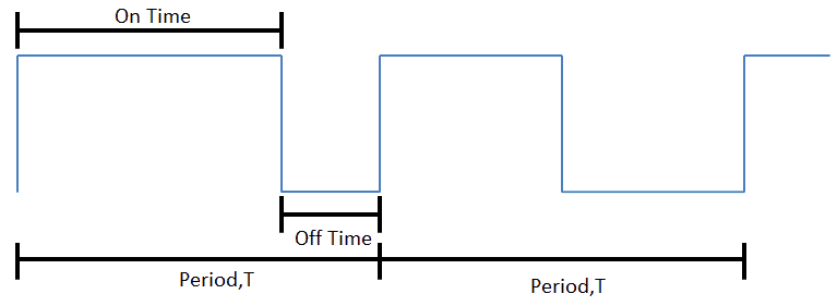
- The figure above shows an example of PWM signal. Note that the frequency and the period is constant. Only the ON time and the OFF time pulse (duty cycle) varies. The higher the duty cycle, the longer the ON time, which means more power will be transmitted to the load. The formula for duty cycle is (Ton/(Ton+Toff))*100%. For example, if the PWM signal is 12V. At 75% duty cycle, 9V is delivered to the load.
- On the other hand, "DIR" is a digital 2-level signal. When at HIGH state, the motor rotates in one direction whilst at LOW state, the motor rotates in the opposite direction. Of course to enable the motor to rotate, besides the DIR pin, there must be duty cycle too :)
In this tutorial, I will be using Cytron UNO (Cytron's version of Arduino) to control the motor driver that controls the motors. CT-UNO has helped a lot in the programming part because it is simple and easy to understand. Of course, there are also other microcontroller that can be used to control the motors. I have used CIKU, another type of microcontroller board to control the motors.
How does MDD10A work?
Basically, MDD10A is a siamese twin of a MD10C motor driver. It has 2 separate PWM ports (PWM1 & PWM2) and DIR ports (DIR1 &DIR2). Most of the basic feature of a MDD10A motor driver are similar to a MD10C motor driver. So, people might ask:
Why do you want create a dual channel motor driver? I can just use 2 motor drivers to drive 2 motors.
Yes, indeed but most people tend to be careless in the setup part of the common GND. If there is no common GND, the motor driver might take the voltage from the microcontroller and will cause weird results. Cytron is always here to make your life easier. Therefore, we have come up with this design to ease your work. You can use it as a mono-channel motor driver or a dual channel motor driver. :D cool right? Plus, MDD10A is cheaper compared to 2 x MD10C. If you would like to see a tutorial on how to use the MD10C motor driver, please click here.
One of the feature, though that I would like to highlight is its support for sign-magnitude and locked anti-phase PWM signal. Ever heard of these terms?
- Sign-magnitude mode
In this mode, you need to use 2 separate signals to control the motor. This is because you need to define the PWM duty cycle for the speed of the motor and the direction of the motor individually.
- Locked anti-phase mode
In this mode, only 1 signal is required to control the speed (PWM pin) and direction of the motor (DIR pin). The magnitude pin that previously controls the speed of the motor in the sign magnitude mode is always at HIGH state, while the direction pin is fed with PWM signals. There are 3 cases over here:
- When the duty cycle is <50%, the motor rotates from the highest speed and goes gradually slower
- When the duty cycle is 50%, the motor comes to halt.
-When the duty cycle is >50%, the motor starts to rotate in the opposite direction until the max speed.
The good news is that you can always set the PWM's duty cycle to 50%, to bring the motor safely to (almost) a halt without causing your battery to charge or raising the supply voltage to dangerous levels.
The bad news is that you have no control over how long it will take the motor to stop, so while electrically this might sound a safe choice, mechanically it is a completely different story. On top of that, if there’s external torque applied to the motor, simply centering the PWM and not providing torque will not stop it (Eg: You will not be able to stop a car rolling down-hill by simply taking your feet off the pedal). Besides that, locked-antiphase mode has lower efficiency then PWM, which results in the motor heating up more. This is because the AC component of the result of low-pass filtering is higher than sign magnitude PWM, because the rate of decay of the current is higher.
(source taken from http://www.modularcircuits.com/blog/articles/h-bridge-secrets/lock-anti-phase-drive/)
Objective: At the end of this tutorial, you should learn the following:-
1. How to connect the motor driver to the motors and to CT-UNO.
2. Control the motors using sign-magnitude mode and locked anti-phase mode using programming, potentiometer and switches.
Components needed:
- 1X MDD10A Motor Driver
- 1X CT-UNO/Arduino UNO board
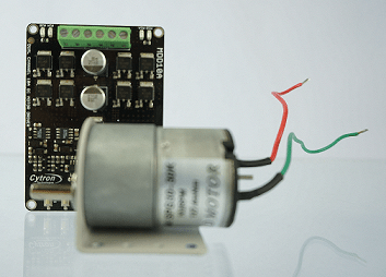
- 2X DC Geared Motors (SPG20/30) series
- 1X Potentiometer (5k/10k/20k/100k)
- 2X small slide switch
- Male to Male Jumper wires
- Female to Male Jumper wires
- test pen/any flat head screw driver
- Breadboard
- USB Cable port (Your android/windwos phone charger cable)
- 12V 2A Power Adapter
- 12V/2.1Ah Power supply (You may use the DC power supply available in your lab as well as long as it is enough to driver the motor)
Mode 1: Sign-magnitude mode
NOTE: PLEASE READ!!!! While you are setting up:
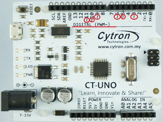
- Please make sure that the pwm 1 and pwm 2 pins of MDD10A are connected to the Arduino's PWM digital pins. To identify which pin can produce PWM signals:
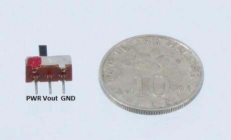
- The diagram below shows the pin connection of the switch and its size.
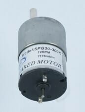
- Bonus knowledge: Do you know how to choose the correct motor for your project? Have you ever wondered what the words written on the motor mean? See the "Model: SPG30-300K"? It is not just a model name. "SPG30" represents the size of the motor. "300K" is known as the gear ratio. This means that 1 rotation of the motor output shaft requires 300 spins inside the motor. Meanwhile "12RPM" meaning there is 12 Rotation Per Minute whilst "1176mNm" represents the torque value. If you run this motor with a 12V power source, you will notice that the rotation is very slow compared to any motor with a smaller gear ratio, such as the SPG30-30K model.
- Make sure that the terminals of the power supply to the motor driver are connected properly to avoid damaging the motor driver. MDD10A does not come with polarity protection.
- Remember to connect the GND pin on the motor driver and the CT-UNO and the negative terminal of the power supply to a common GND. Otherwise, the motor will not function optimally.
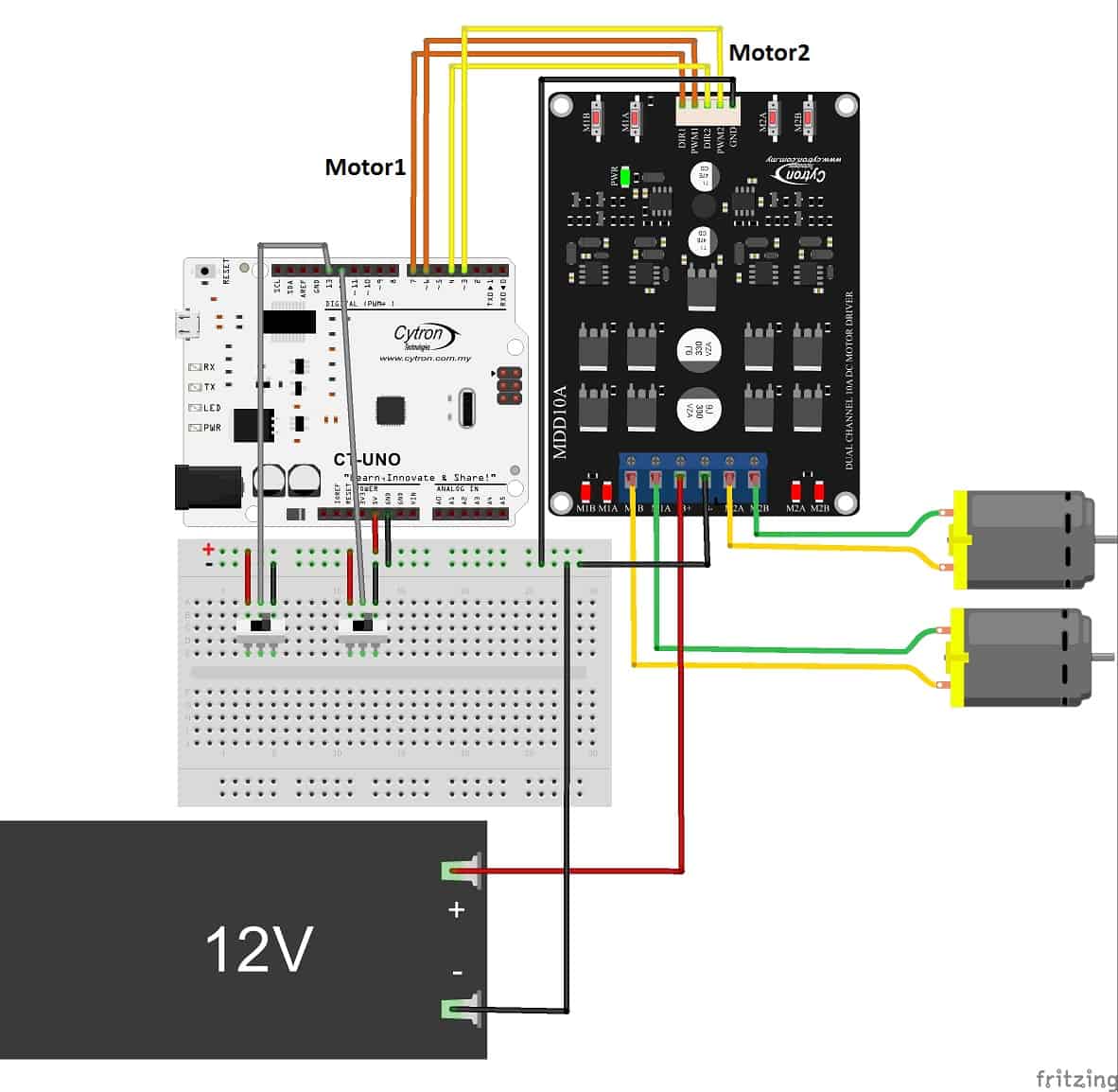
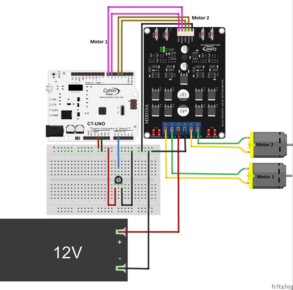
(a) Controlling the motor speed with program
Set up
Programming
[code lang="c" highlight=""] //define pin name #define dir_1 7 #define pwm_1 6 #define switch_1 13 #define switch_2 12 #define dir_2 4 #define pwm_2 3 #define pot A1 //potentiometer void setup(){ //declare pins as INPUT/OUTPUT pinMode(pwm_1,OUTPUT); pinMode(dir_1,OUTPUT); pinMode(pwm_2,OUTPUT); pinMode(dir_2,OUTPUT); pinMode(pot,INPUT); pinMode(switch_1, INPUT); pinMode(switch_2, INPUT); Serial.begin(9600); //I am using Serial Monitor instead of LCD display } void loop(){ int pwm_value; for (pwm_value=0;pwm_value<=255;pwm_value++){ digitalWrite(dir_1,digitalRead(switch_1)); //controls the direction the motor digitalWrite(dir_2,!digitalRead(switch_2)); analogWrite(pwm_2,pwm_value); //increase the speed of the motor from 0 to 255 analogWrite(pwm_1,(255-pwm_value)); //decrease the speed of the motor from 255 to 0 Serial.println("PWM:"); Serial.println(pwm_value); //Display the value of PWM delay(100); } while(1) continue; //terminate the program }[/code]
Code overview
- If you noticed, I didn't use any library here. The standard commands in Arduino doesn't need us to declare the library. Also, we will not be using LCD Display here because of the limited pins on the UNO.
- The pin numbers are assigned with names for easier understanding and convenience. You can customize the names to your liking.
- The for loop repeats for 256 times which is 100% duty cycle. Why 256 and not 100 since it is 100%, you say? When I assign the values to the pwm pins, I used the command "analogWrite(pin,X)". X is an 8-bit value i.e. from 0 to 255. So, by calculating the resolution, each step sends 0.196V.
- I used Serial Monitor instead of LCD because of the lack of PWM pins. Initially, I used a keypad shield LCD which uses pin 4- pin 9 digital pins. So, I could only use pin 0-3 as pin 10-13 were not available on the shield and only pin 3 has PWM function but I need 2 pins with PWM function to demonstrate the MDD10A. If you still want to use an LCD display, no problem. This tutorial will teach you how to create PWM signal using other pins instead of the predefined PWM pins from Arduino board.
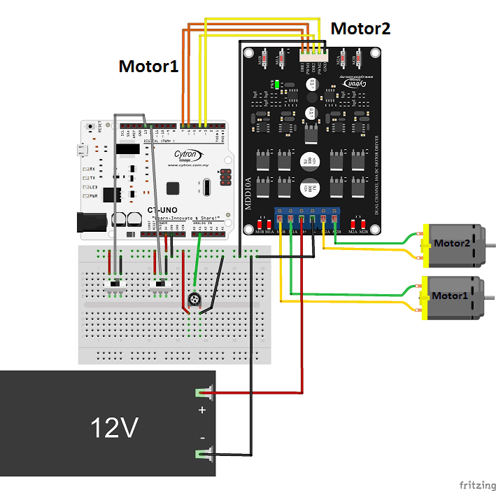
(b) Controls the speed of the motor by potentiometer
Set up
//define pin name
#define dir_1 7
#define pwm_1 6
#define switch_1 13
#define switch_2 12
#define dir_2 4
#define pwm_2 3
#define pot 1 //potentiometer
void setup() {
// put your setup code here, to run once:
pinMode(pwm_1,OUTPUT);
pinMode(dir_1,OUTPUT);
pinMode(pwm_2,OUTPUT);
pinMode(dir_2,OUTPUT);
pinMode(pot,INPUT);
pinMode(switch_1, INPUT);
pinMode(switch_2, INPUT);
Serial.begin(9600); //I am using Serial Monitor instead of LCD display
}
void loop() {
// put your main code here, to run repeatedly:
int pwm_value=0;
int reading=0;
int prev_reading=0;
//controls the direction the motor
digitalWrite(dir_1,digitalRead(switch_1));
digitalWrite(dir_2,!digitalRead(switch_2));
//controls the speed of the motor
for (int i=0;i<5;i++) //gets the average value of the pot value for better accuracy
reading+= analogRead(pot);
reading/=5;
pwm_value = reading>>2; //convert the 10-bit values to 8-bit values
analogWrite(pwm_1,pwm_value);
analogWrite(pwm_2,pwm_value);
Serial.println("PWM:");
Serial.println(pwm_value); //Display the value of PWM
delay(100);
}
Code overview
- "pwm_value = reading>>2; //convert the 10-bit values to 8-bit values"
When we analogRead(pot), it returns a 10-bit value from 0 to 1023. Later we need to analogWrite(pwm_1,pwm_value). As mentioned, in analogWrite(pin,X), the X has to be an 8-bit value from 0 to 255. Therefore, to convert a 10-bit value to 8-bit value, I am using bit shift which uses variable >> number_of_bits. So I shift the 2 bits to the right which means that I remove 2 bits to become 8 bits.
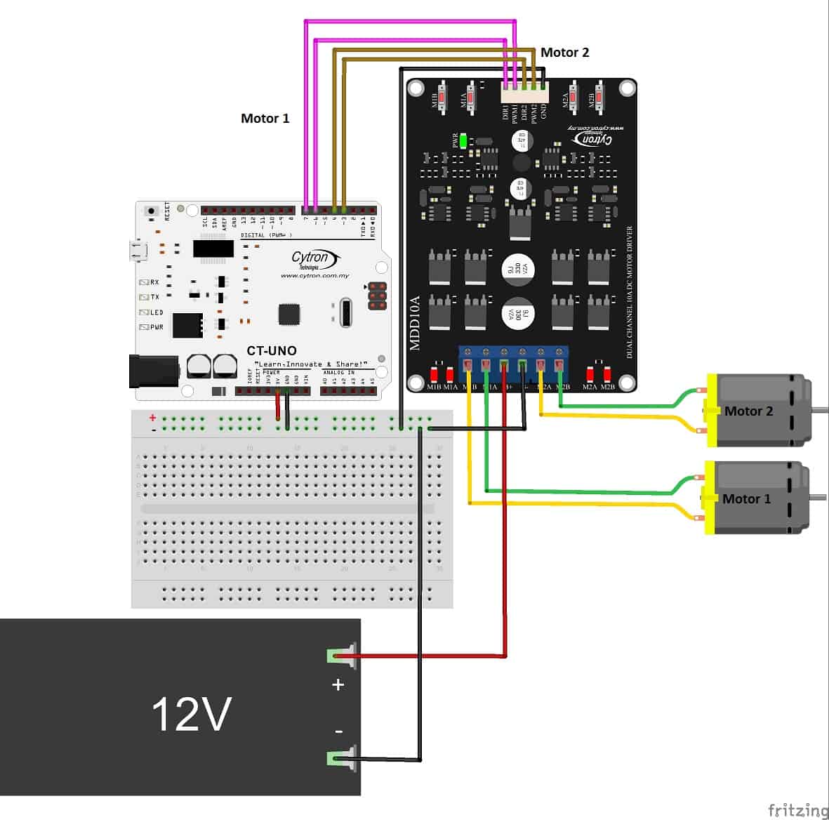
Mode 2: Locked anti-phase mode
(a) Controlling motor speed by program
Set up
Program
// define pin name
#define pwm_2 4
#define pwm_1 7
#define dir_2 3
#define dir_1 6
void setup() {
pinMode(pwm_2, OUTPUT);
pinMode(pwm_1, OUTPUT);
pinMode(dir_1, OUTPUT);
pinMode(dir_2, OUTPUT);
Serial.begin(9600);
//Serial.println("DIR");
}
void loop() {
int pwm_value = 0;
int opposite_i;
digitalWrite(pwm_1,HIGH);
digitalWrite(pwm_2,HIGH);
for(int i=0;i<=255;i++){
analogWrite(dir_1,i);
opposite_i=255-i;
analogWrite(dir_2,(255-i));
delay(120);
Serial.println(i);
}
while(1)
continue;
}
Code overview
- The coding concept is the same as the previous ones. The only changes made are the pwm_1 and pwm_2 pins are set to HIGH state at all times whilst the dir_1 and dir_2 pins are connected to digital pins with PWM i.e. pin 6 and pin 3.
- Initially, the dir_1 pin has 0% duty cycle whilst dir_2 pin has 100% duty cycle but both still rotate at the same direction at maximum speed.
(b) Controlling motor speed by potentiometer
Set up
Program
#define pwm_2 4
#define pwm_1 7
#define dir_2 3
#define dir_1 6
#define pot A1
void setup() {
// define pin name
pinMode(dir_1, OUTPUT);
pinMode(dir_2, OUTPUT);
pinMode(pwm_1, OUTPUT);
pinMode(pwm_2, OUTPUT);
pinMode(pot,INPUT);
Serial.begin(9600);
}
void loop() {
int reading = 0;
int output=0;
int opposite_output=0;
digitalWrite(pwm_1,HIGH);
digitalWrite(pwm_2,HIGH);
for (int i=0;i<5;i++)
reading+= analogRead(pot);
reading/=5;
output=reading>>2; //convert 10-bit to 8-bit
opposite_output=255-output;
analogWrite(dir_2,output);
analogWrite(dir_1,opposite_output);
delay(30);
Serial.println("DIR");
Serial.println(output);
}
Code overview
- Again, the concept is similar to sign-magnitude mode but the pin connection is changed. Now the PWM pins are always HIGH whilst the DIR pins are connected to digital pins which gives out PWM signals.
I hope you find this tutorial useful! If you have any questions please feel free to post it in our forum! If you feel that this tutorial is helpful, let me know at the comment section below! Thank you! :D
Attachment (code):