 International
 Singapore
 Malaysia
 Thailand
 Vietnam
Your shopping cart is empty!

IRIV Agriculture Box tutorial
- Abdulkareem Bageri
- 15 Sep 2024
- Project
- Intermediate
- 38
In this project guide you will learn how to build IRIV Agriculture Box. you will know how to wire the components, how to control and program the system and how to design your dashboard.
Hardware
- IRIV PiControl
- 24DCV power supply
- 3 x 24V relay
- 2 x 24V DC Pump
- Push-button
- AC Socket
- Industrial Grade RS485 Temperature & Humidity Sensor
- 3 in 1 moist sensor
Connection Diagram
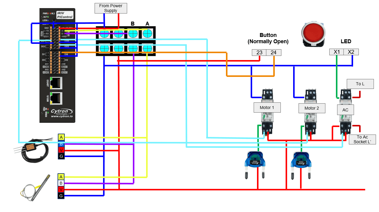
Note : the DC voltage used is 24V.
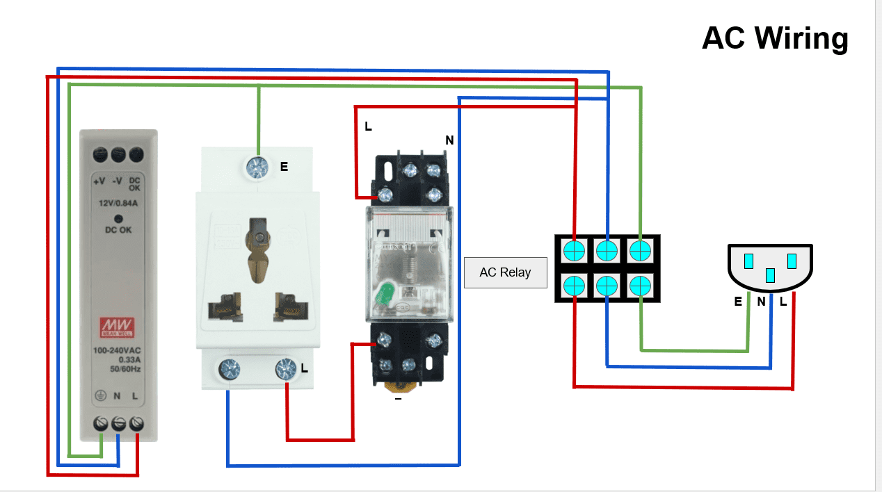
Note: Please remember to handle all connections with care and double-check connections for accuracy.
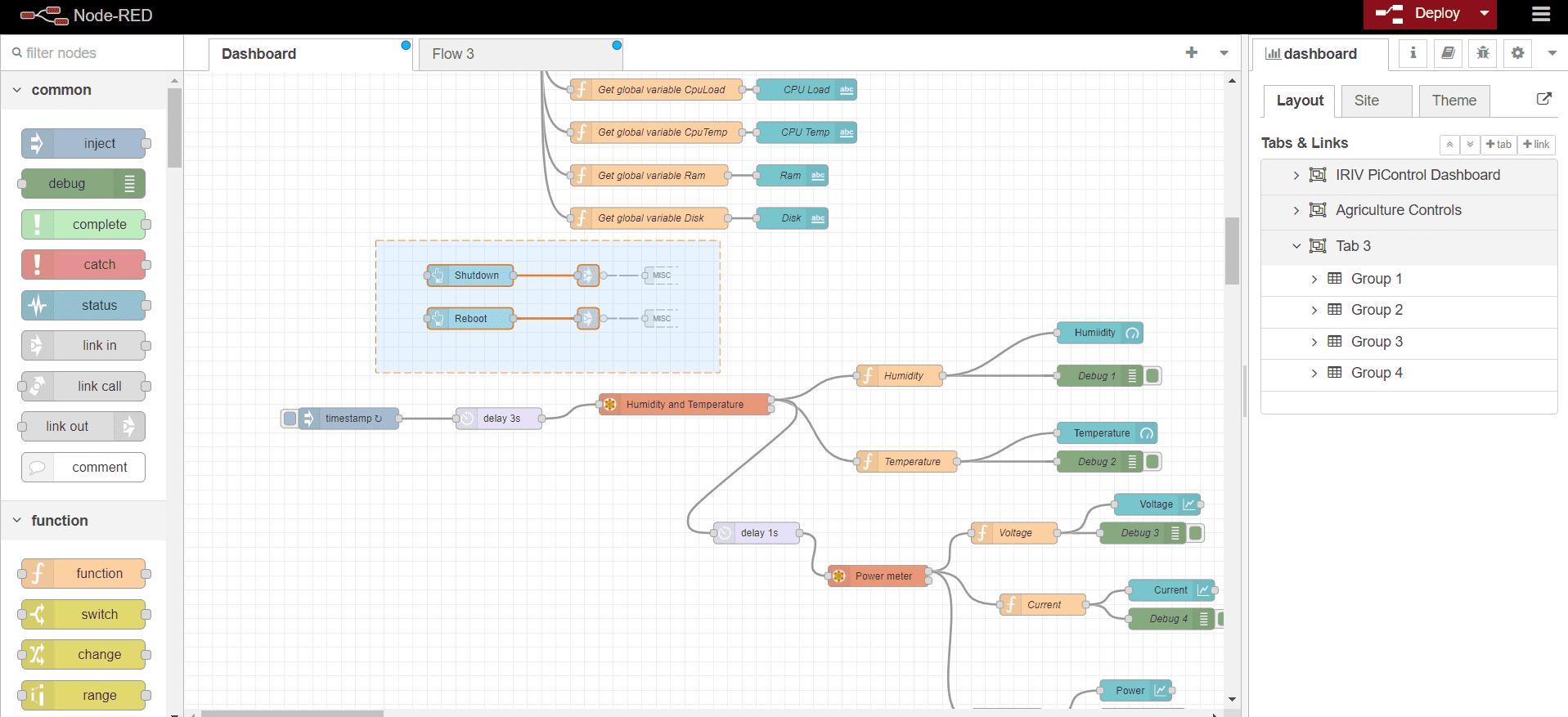
1- Dashboard
Lets start with setting up you dashboard.
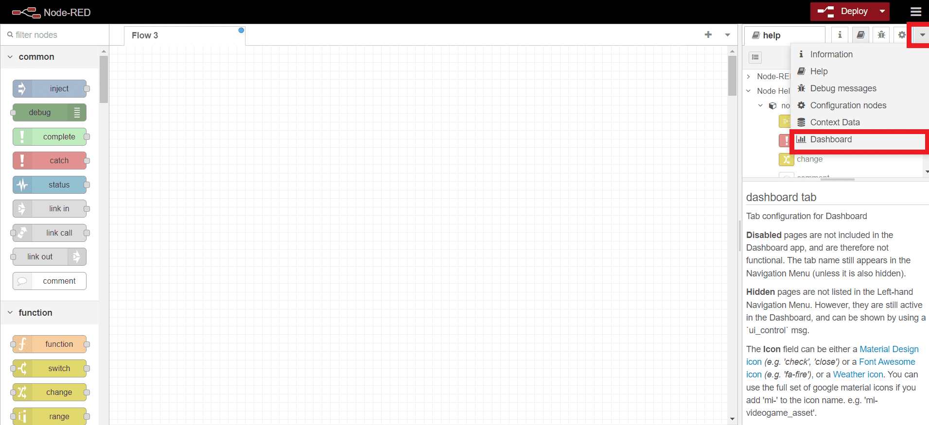
Click on the down arrow in the side platter >> and click on Dashboard.
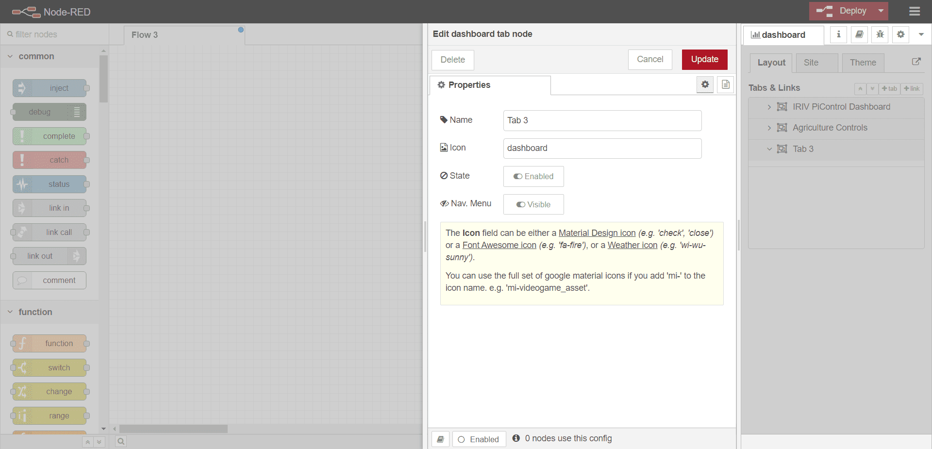
Click on "Tab" button to create a new tab.
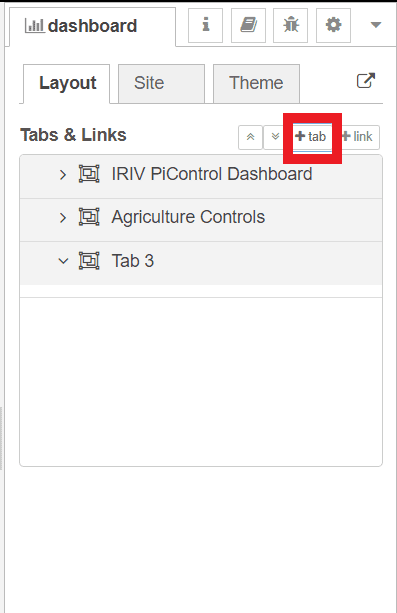
You can change the name of the tab by click on it.
By click link you will ad a group. add (4) groups under your tab.
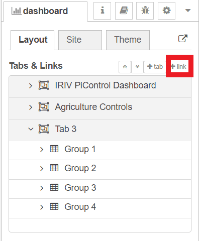
Note : you can specify a custom name for your group.
2 - System
Now, lets start customizing your first group, which will contain main system controls.
IRIV have a dashboard already insatalled, from there copy the Button, LEDs & Buzzer nodes and paste it to your new flow.
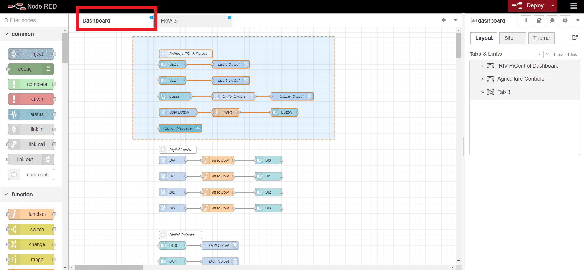
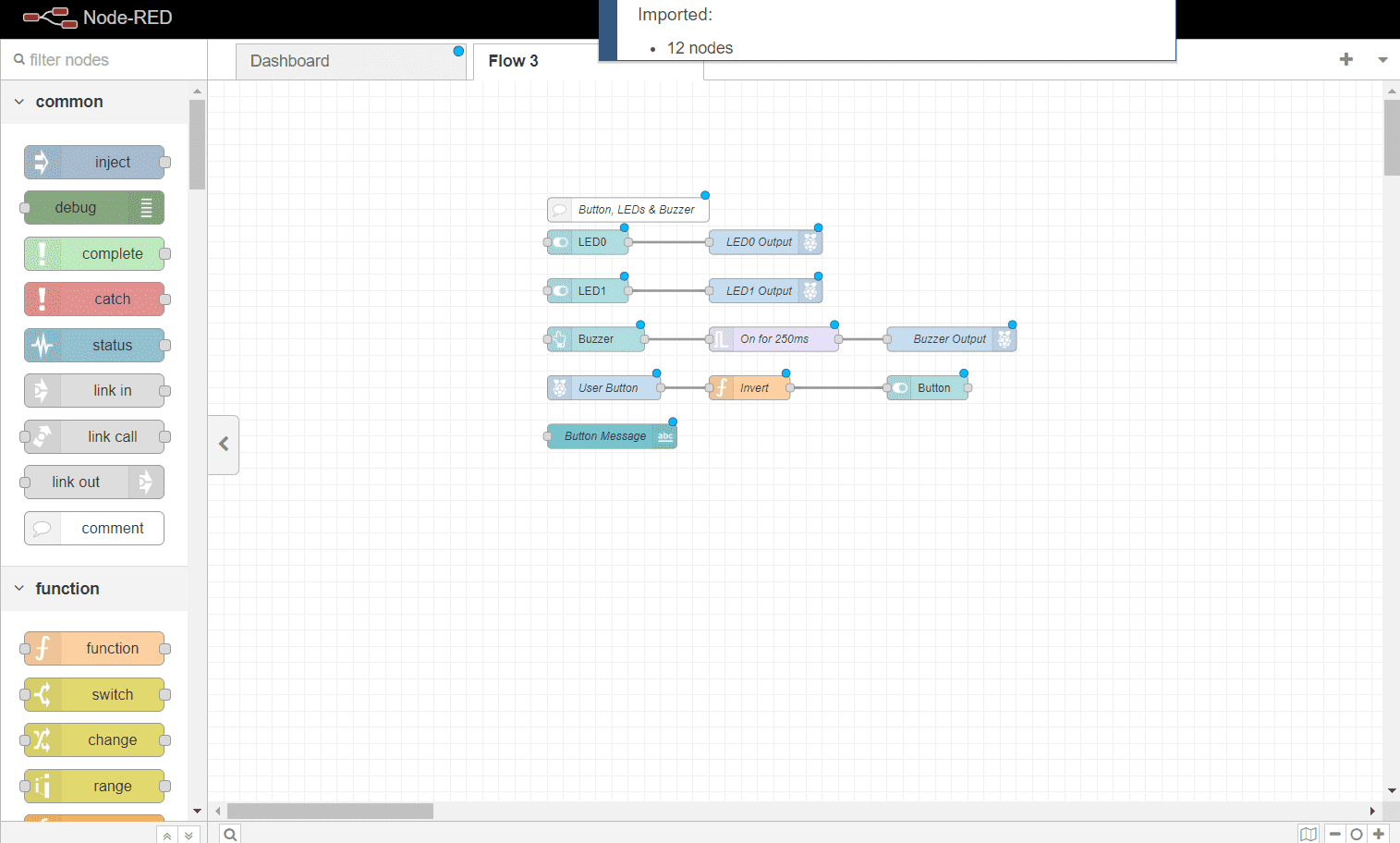
You will also need to use the Shutdown and reboot button. so copy it to your new flow.
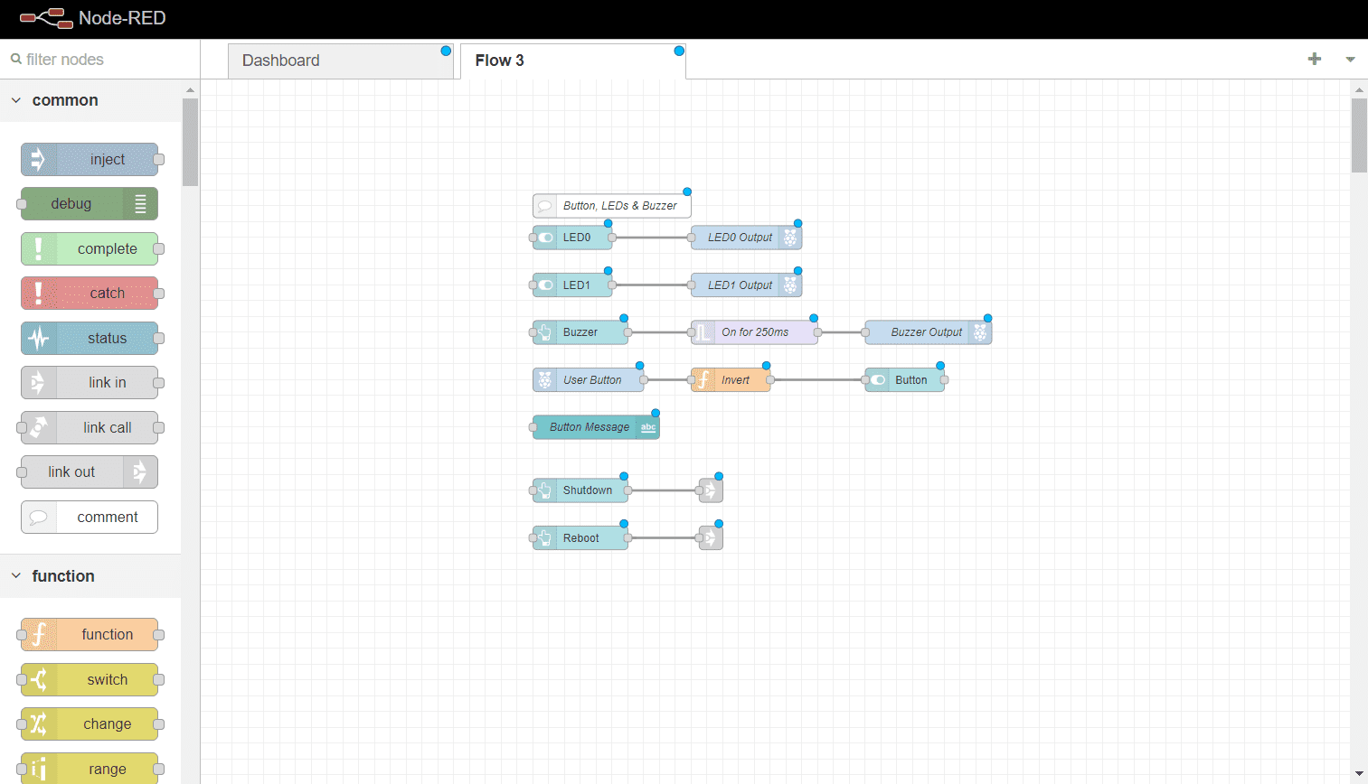
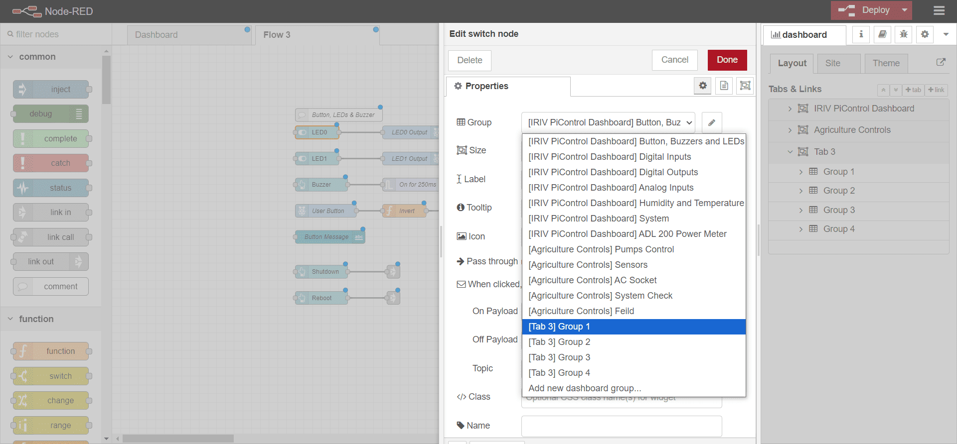
Click on LED0 and change the group to your new tab first group. do the same for LED1, buzzer, Button, Button massage, Shutdown and Reboot.
Now you have your first group ready.
3 - AC Socket
Now lets make our second group. this group is customize for the control of the AC socket. the relay is controlled manually from the push button or from the button on dashboard.
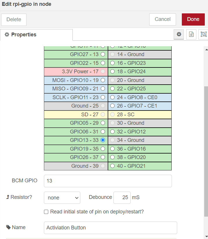
From the plateer, drag "rpi - gpio in" node. we will recive the push button signal throgh this node.
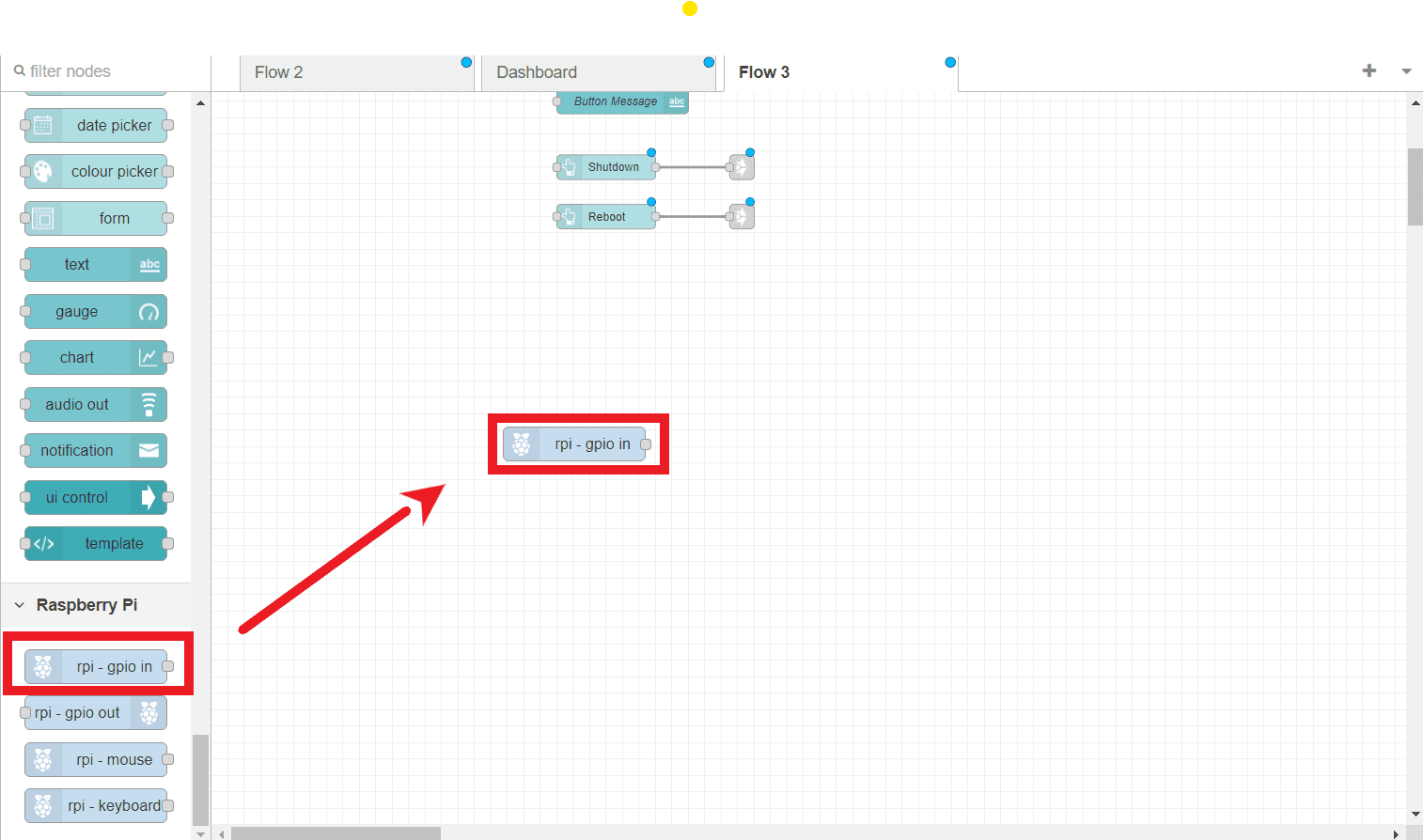
Double click on the node and set it properties as following >> set the pin to GPIO13, and name it as "Activation Button" , you can refer to the datasheet for more info.
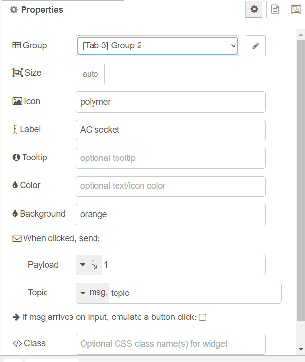
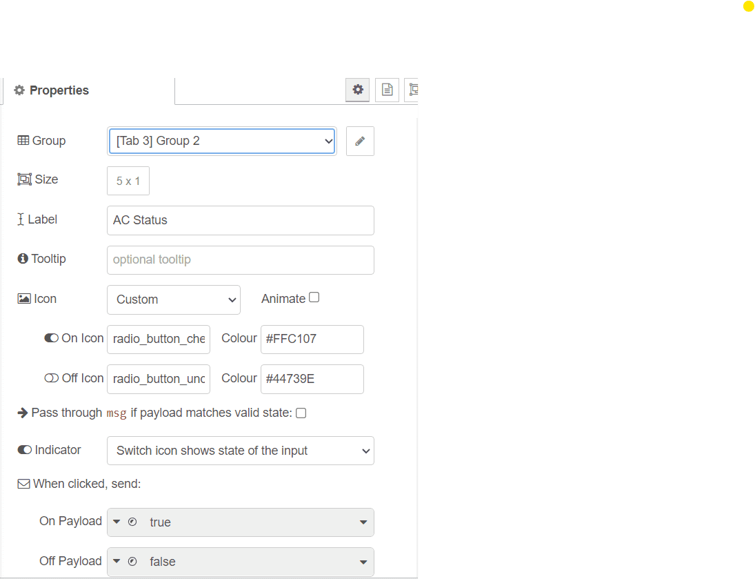
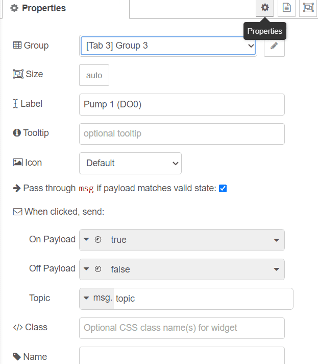
Now drag a button from the platter, this node is to control the relay throgh the dashboard button.
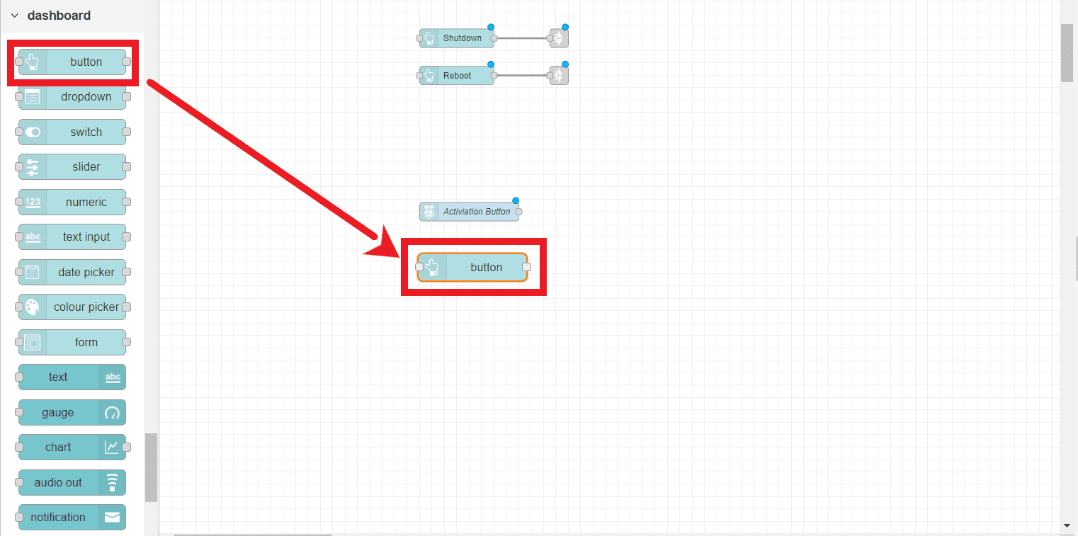
Double click on it and ensure you add it to the second group and set the properites as shown below.
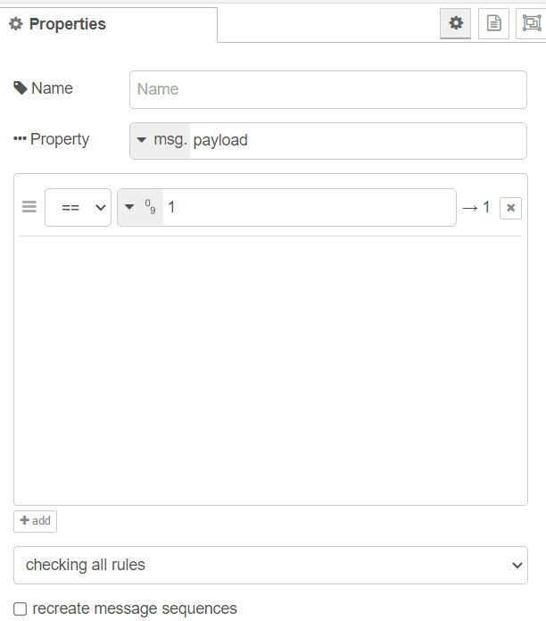
Next, drag a switch to your flow.
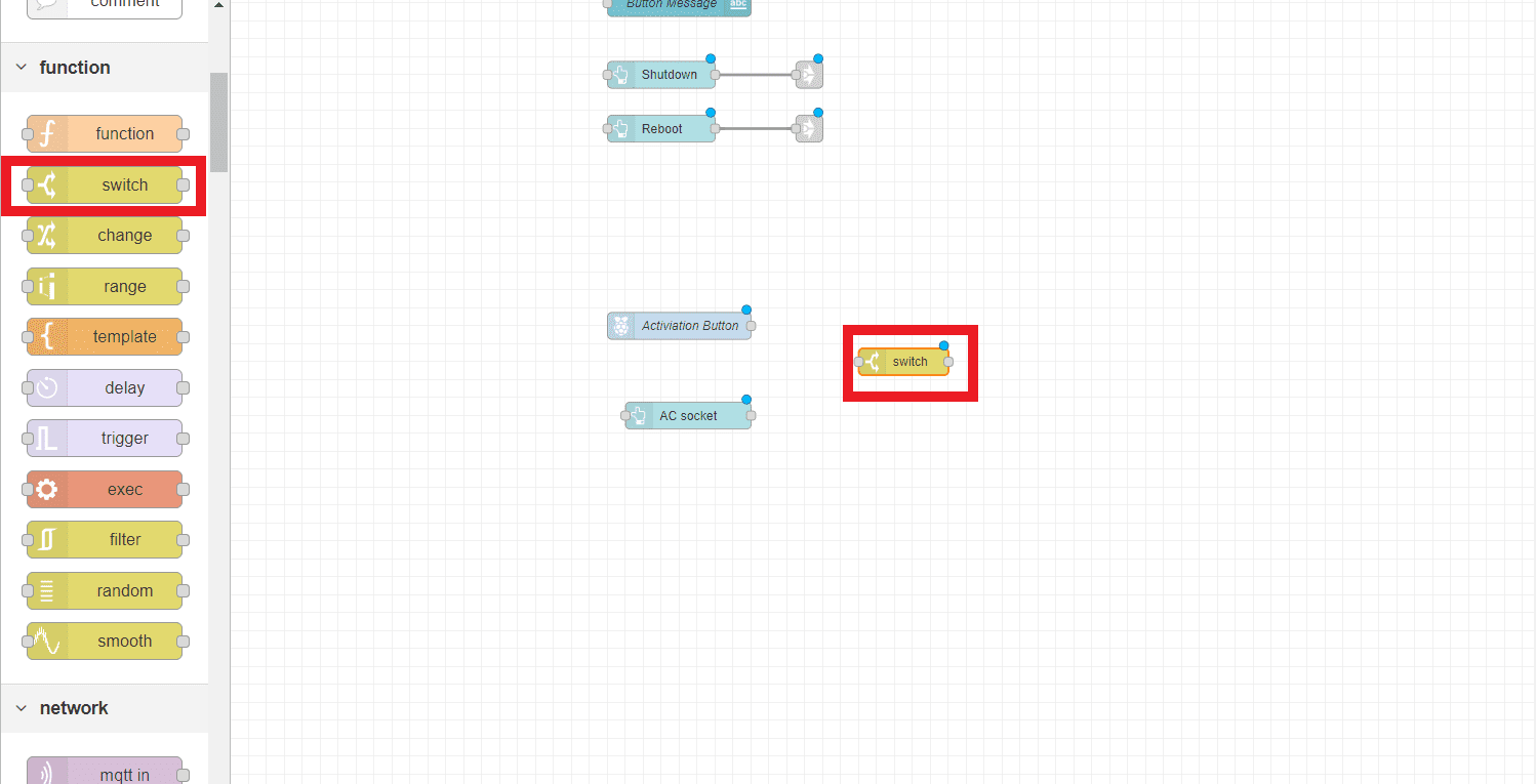
Set the switch as shown in the image below, ensure it gives a numric value of 1.
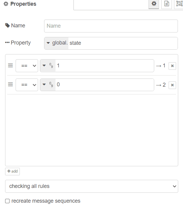
Drag a second switch to the flow.
Set the prperties as shown below.
Set the proberty to: "global. state"
give the nodes two numiric output and set one of them to 1 as the other to 0.
Drag two (Change) nodes to your flow.
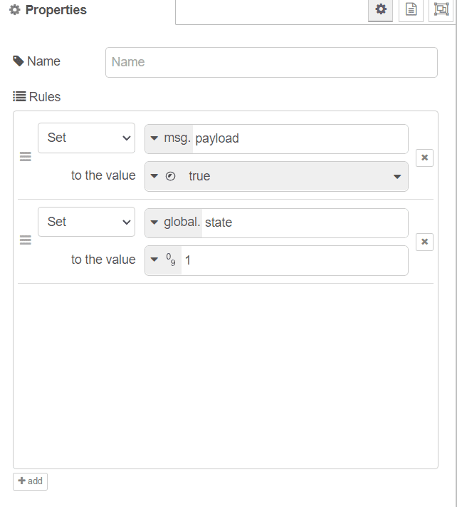
Set the upper one rules to the following.
First one is to set the msg.payload to (Bool) False
Second one is to set the global.state to (Num) 0.
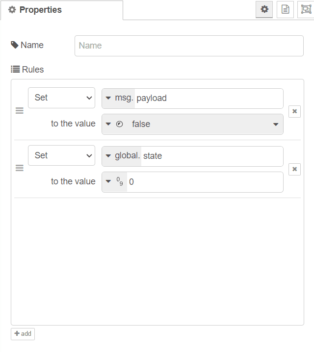
Set the Lower one rules to the following.
First one is to set the msg.payload to (Bool) True.
Second one is to set the global.state to (Num) 1.
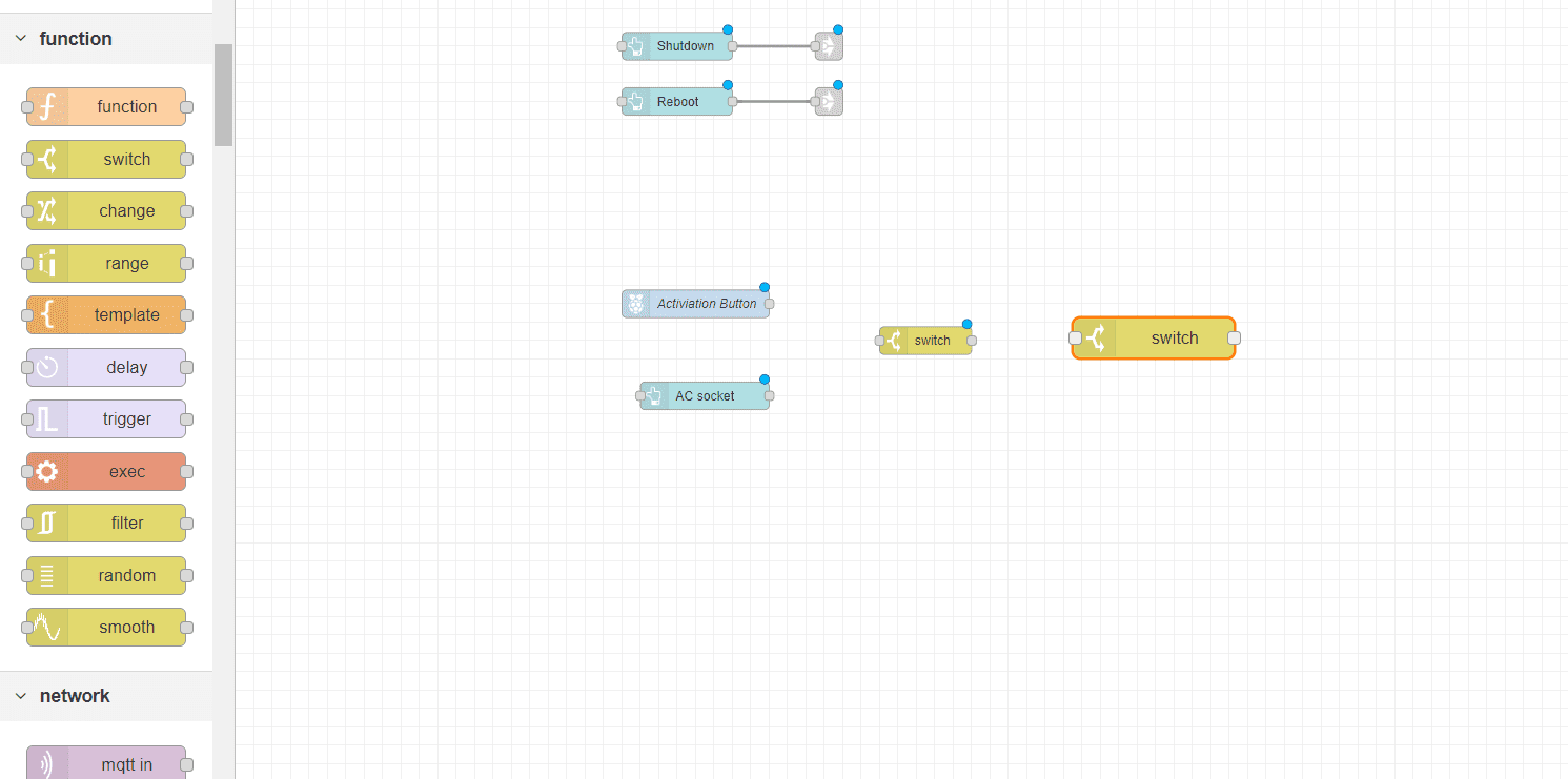
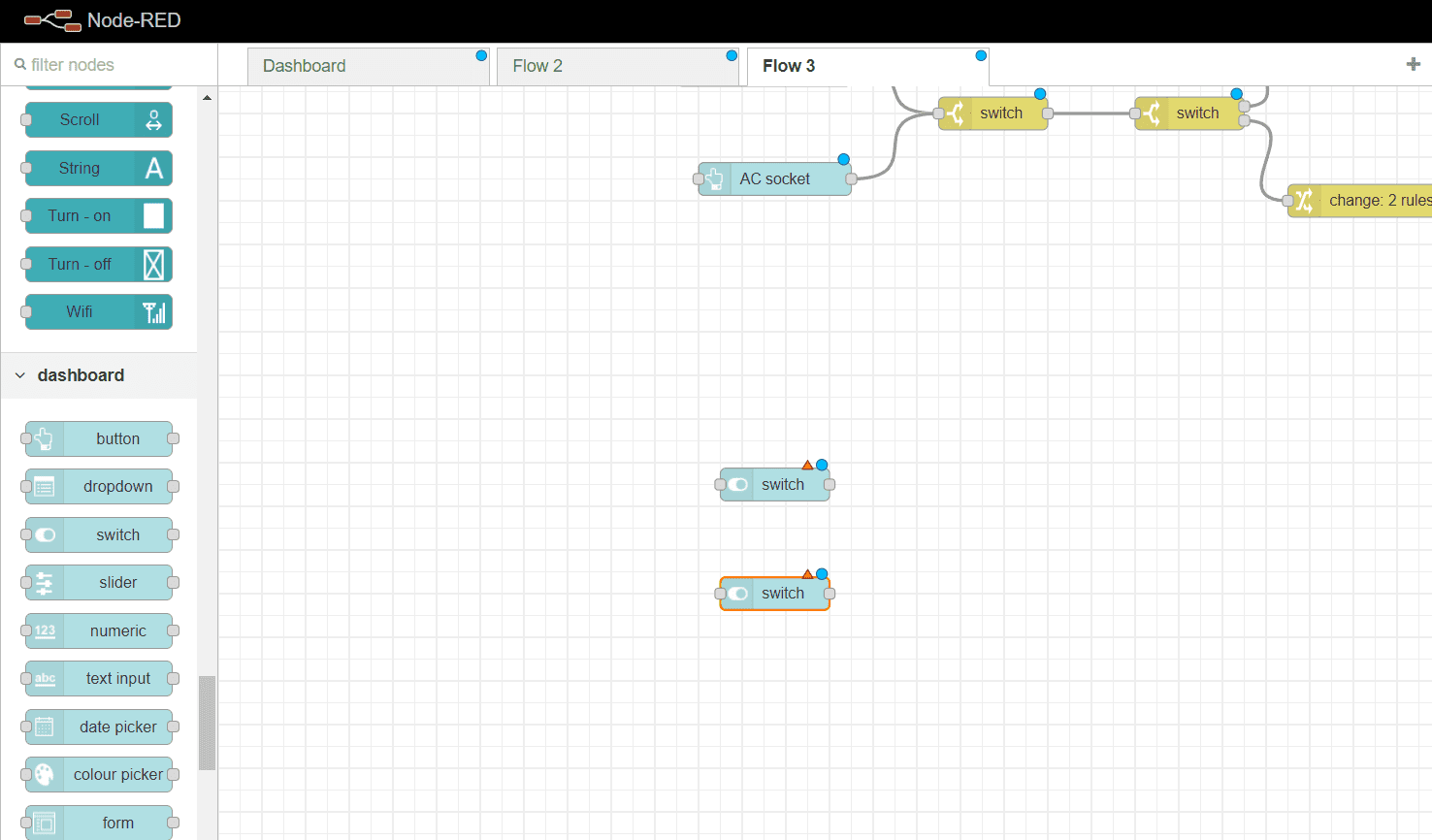
Drag a switch node to your flow.
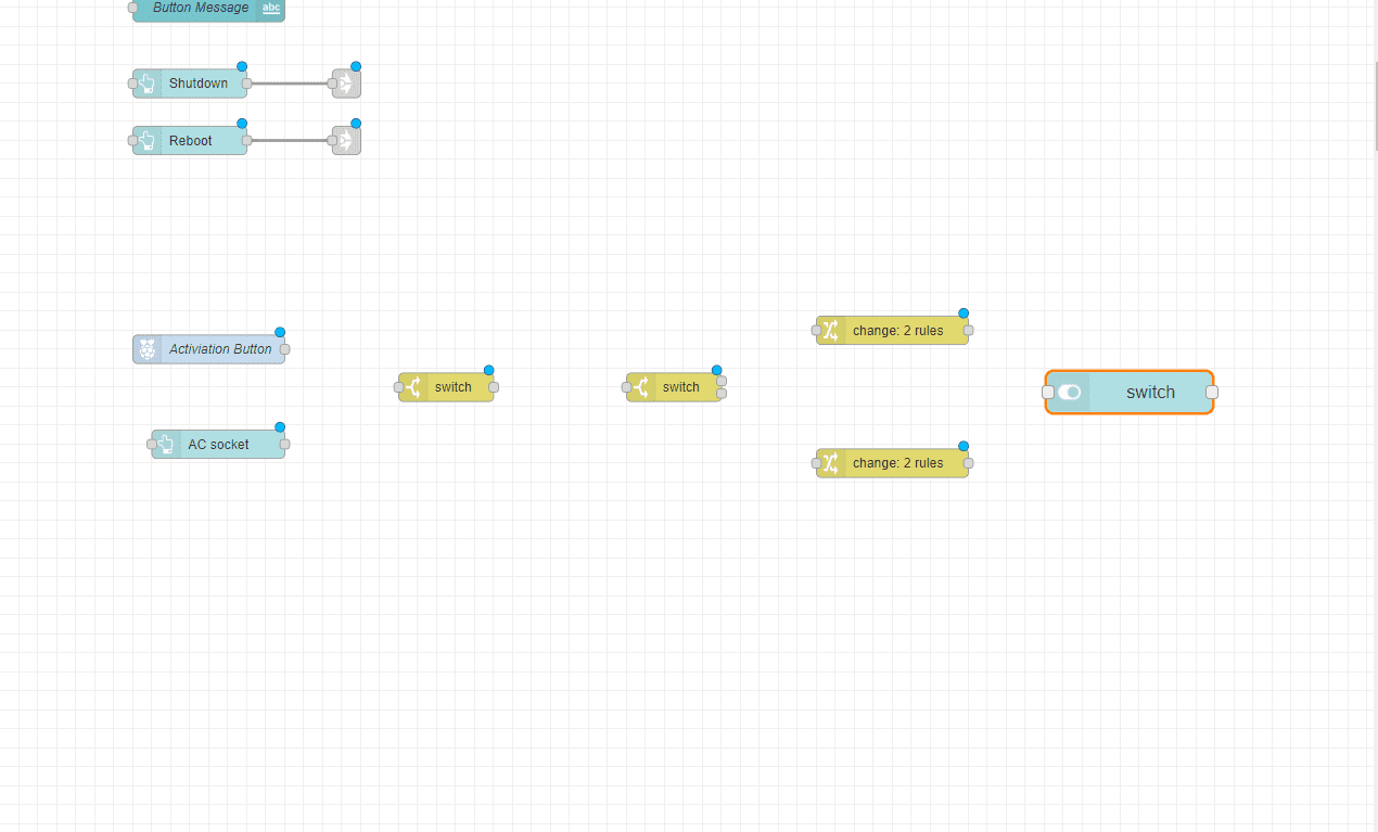
Ensure to add it to the second group. this node will work as inicator of the AC state
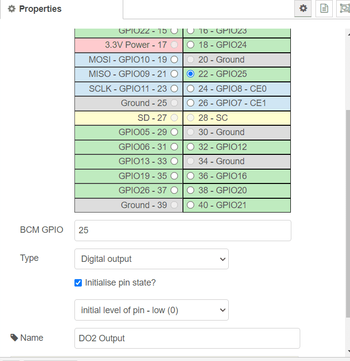
Now drag an output node (rpi - gpio out). this node is to control the relay.
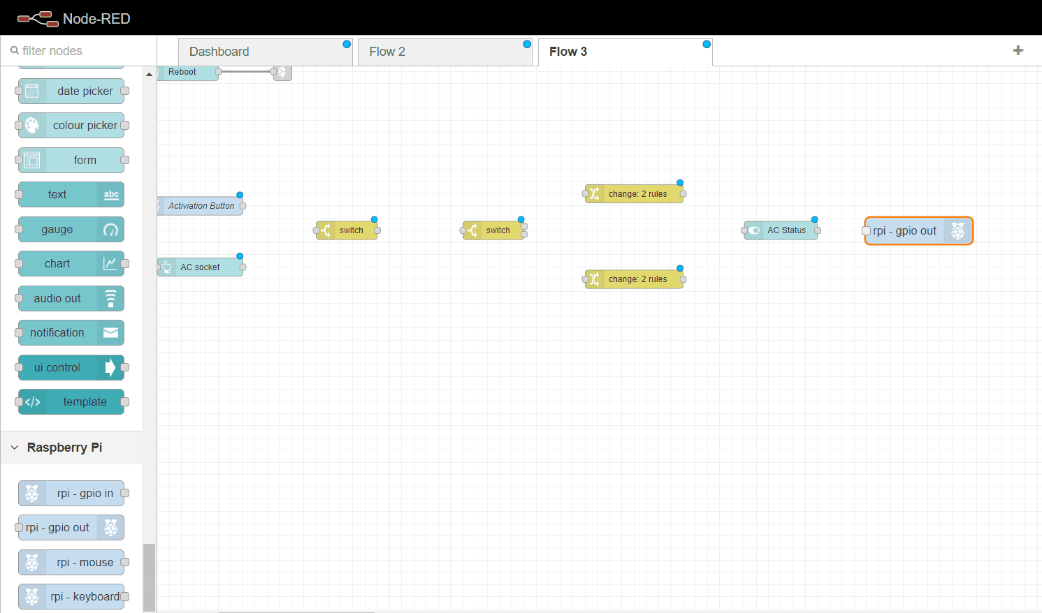
Set the output node to GPIO25 and initil level of pin to 0.
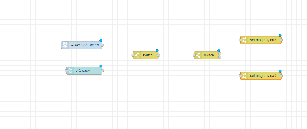
Lastly for this group is to connect the nodes.
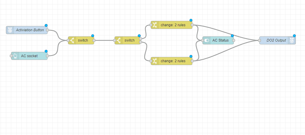
Now you have your second group ready
4 - Controls
The next group is to control the Water pumps throgh the 24V relays.
Drag 2 switchs to your flow, one for each pump
Add each of the switches to the third group and label them as Pump 1 and Pump 2.
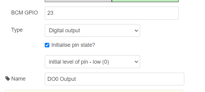
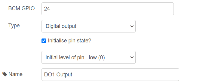
Drag GPIO output pin for each pump.
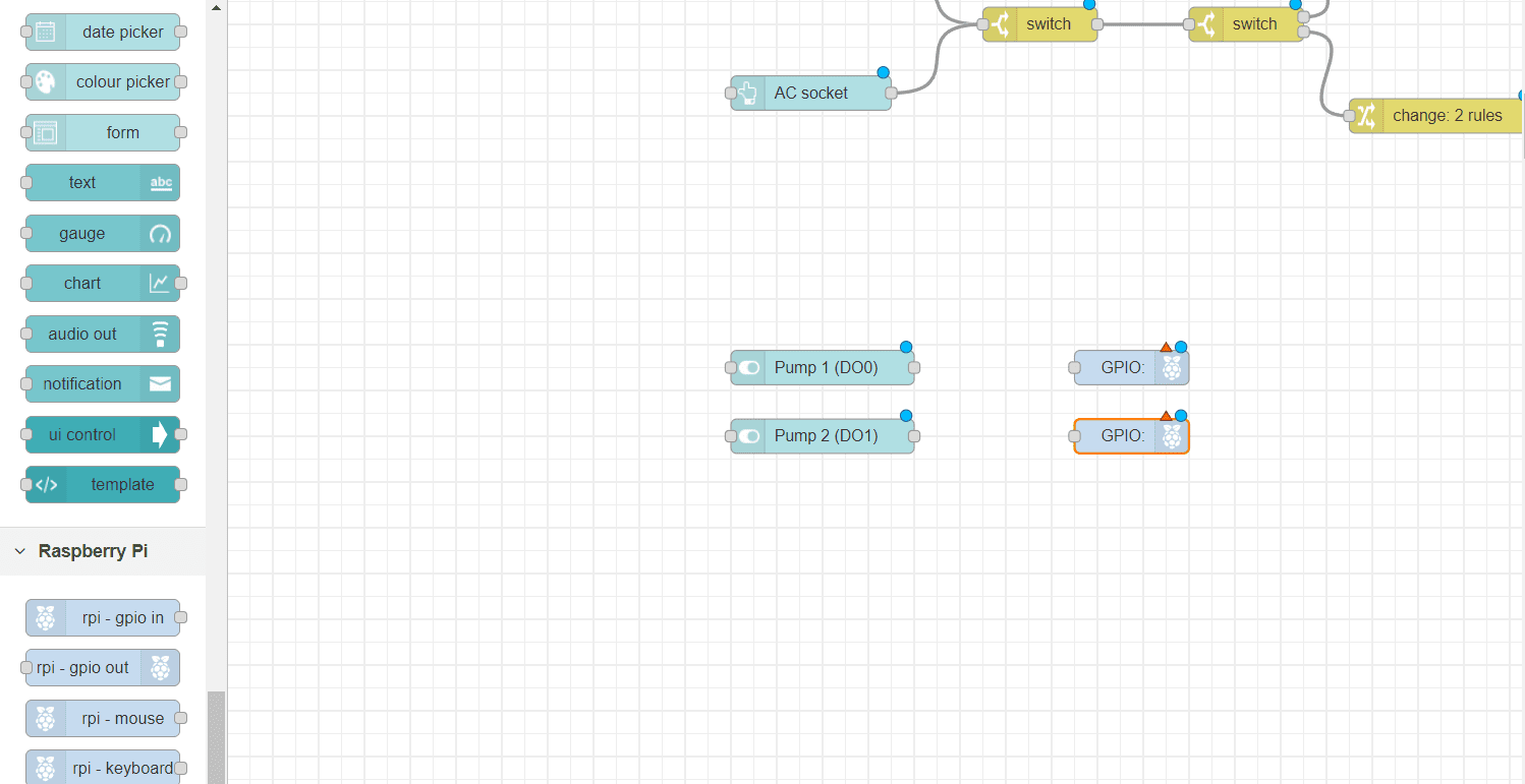
Set the first one to GPIO23 and the second to to GPIO24. amd initilze them to be 0.
Connect the nodes as shown.
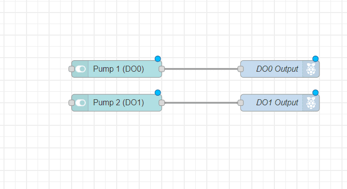
Now you have a group for controlling the pumps
5- Sensors
Setting the Addesses and Baud rates
To get readings out of the senor we must ensure both sensor are working on the same baud rate and they should have diffrent id.
By defaultTemperature and humidity sensor have a buad rate of 9600 and an address of (1).
While the moist sensor buad rate 4800 and address of (1) by default.
First, we'll set the Unit ID for the Temperature and humidity sensor. This ID will be used in our code later to get the readings. To do this, we need to access the DIP switch on the sensor's PCB. Gently open both ends of the sensor, one at a time.
Next, carefully remove the PCB from the metal shell. You'll find the DIP switch on the PCB, which determines the Unit ID. For
this tutorial, we'll set the Unit ID to 2. Refer to the datasheet for detailed instructions on setting the Unit ID.
There is a tutorial avaliable on how to use this sensor.
After that we will need to set the buad rate of the moist sensor to 9600. See this tutorial to know how to change the buad rate.
Code Programming
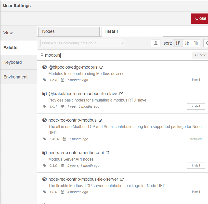
For the sensor group we are going to install a palette, go to the palette manager >> and install "node-red-contrib-modbus".
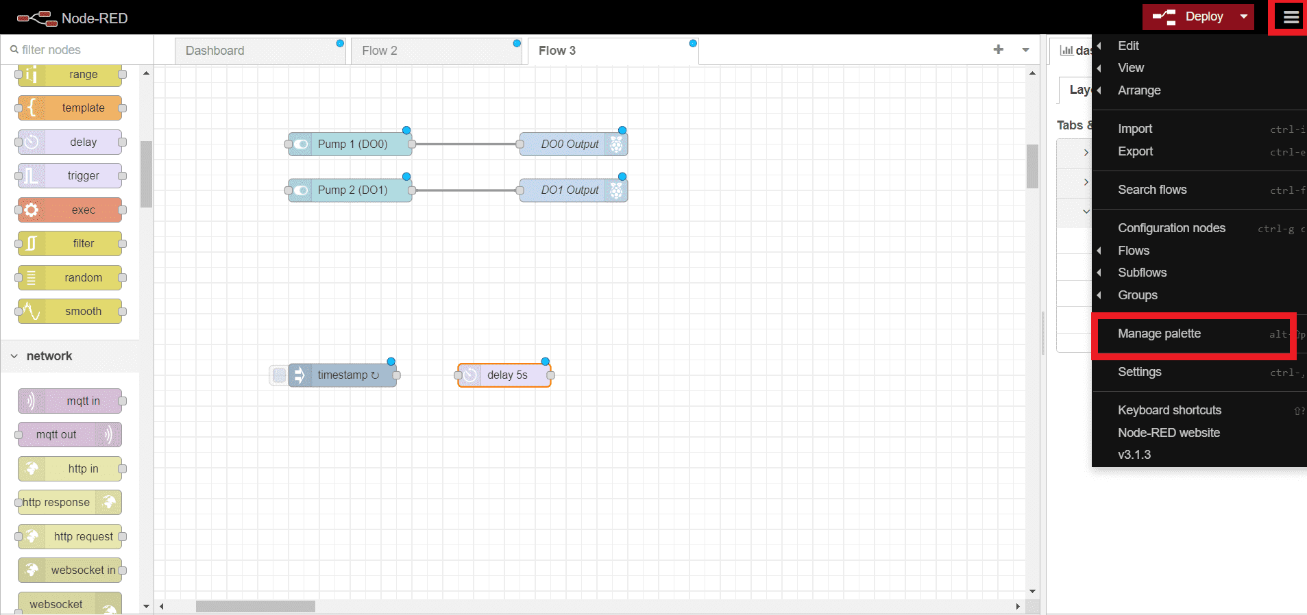
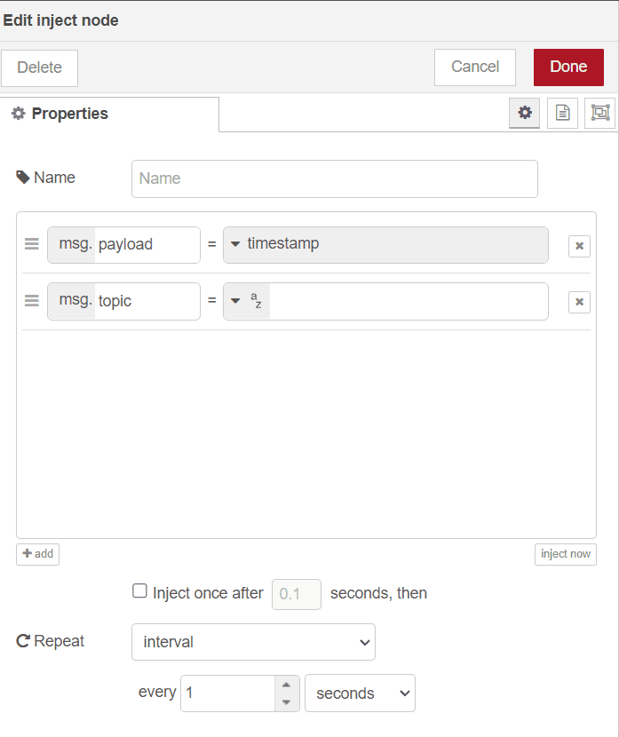
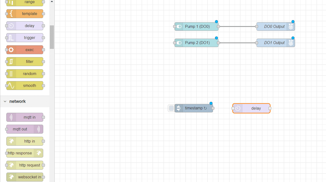
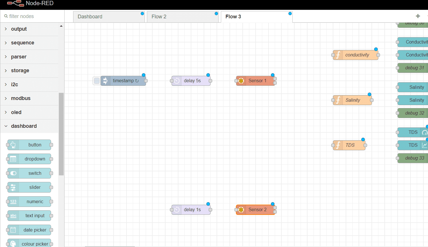
Drag an inject to your flow
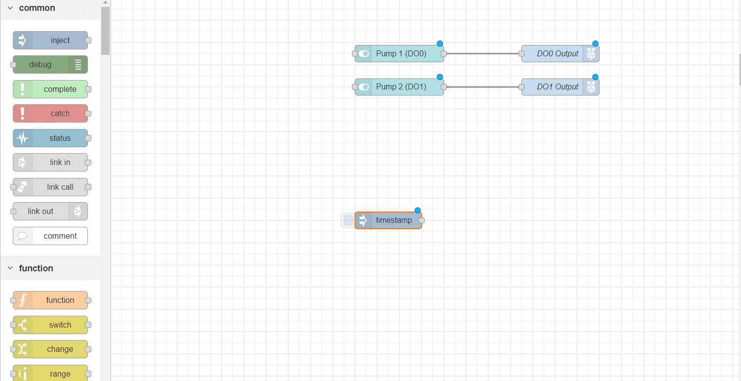
Double click on the node and add interval for every 1 second.
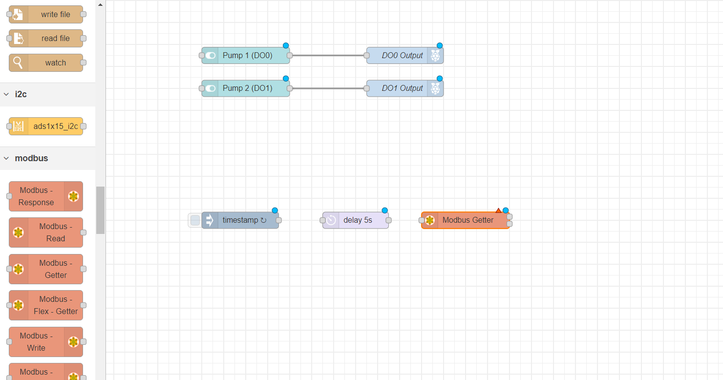
Now add a delay set it to 5 seconds. this will hold the first signals for 5 second and befor it is recived by the next node.
Now, add a Modbus getter node to your flow, this one will be for the moist sensor.
Set the Unit-id to 1 (defult for this sensor) , FC 3 : Read Holding Register, address 0 and quantity to 5.
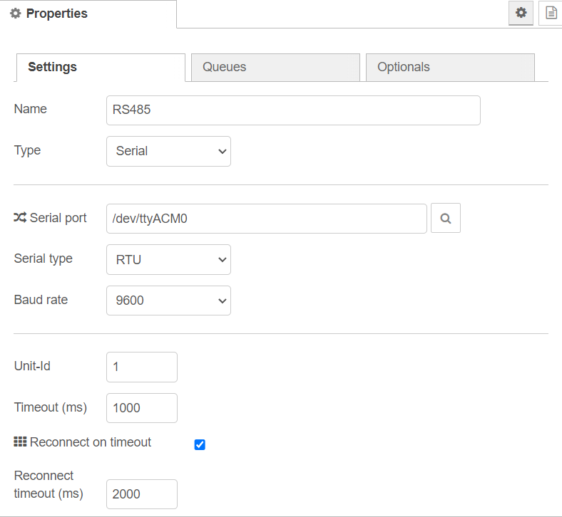
And create a new server.
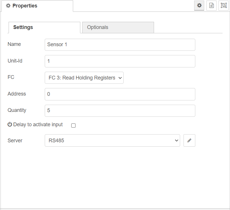
Give it a name of your choice, Type: Serial, Serial port: /dev/tty/ACM0 , Serial type : RTU and baud rate to 9600.
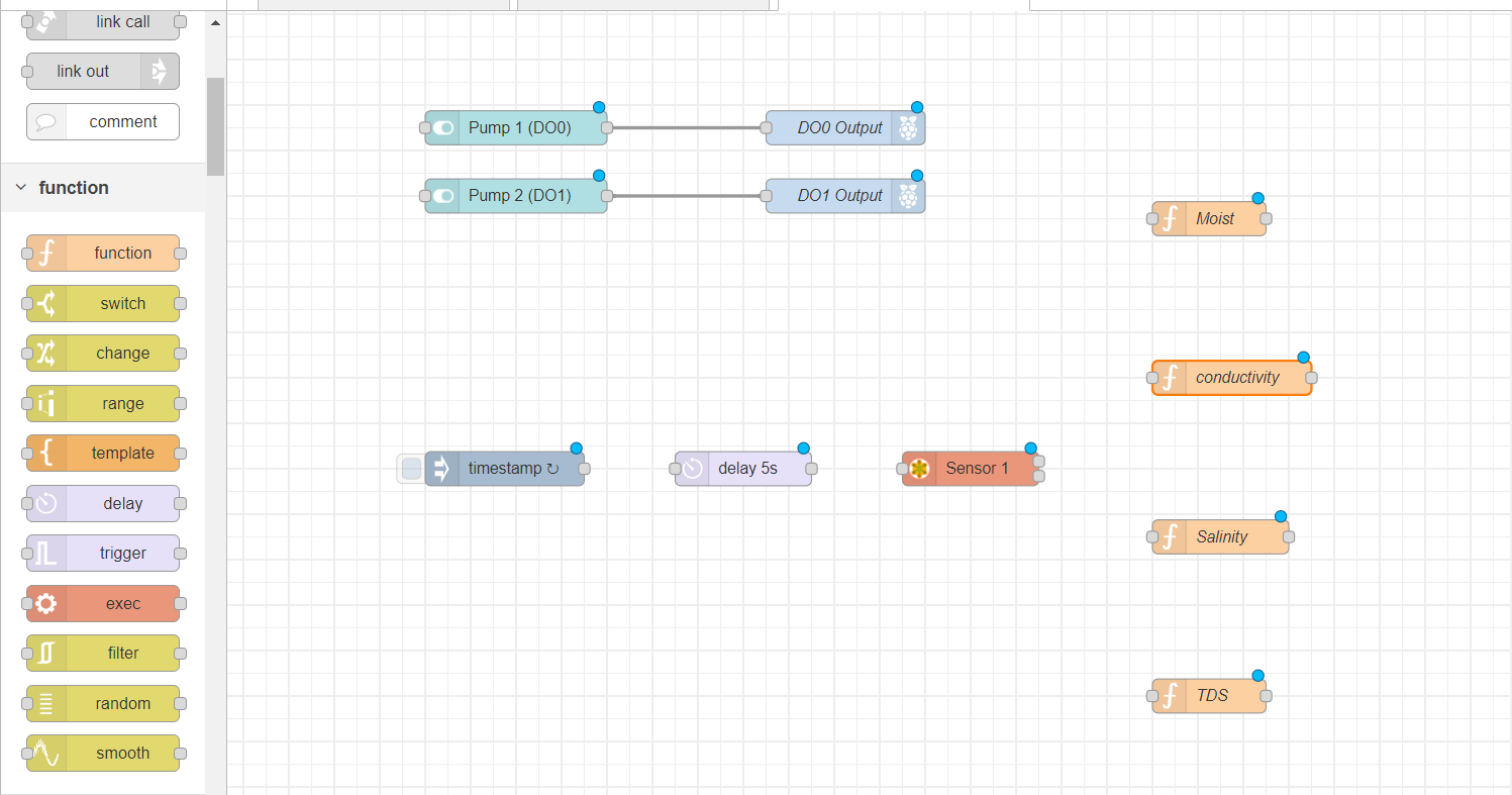
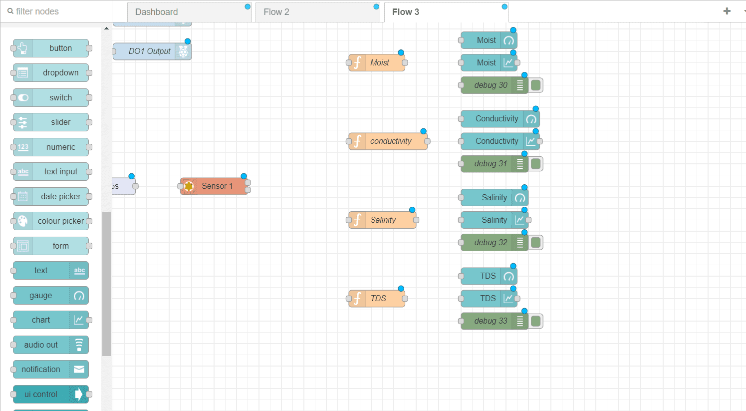
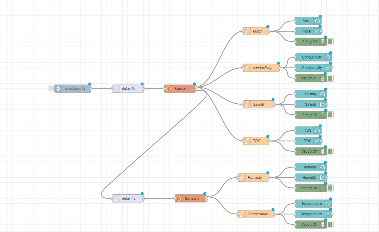
Add 4 different function to you flow, these functions will be for moist, conductivity, salinity and TDS (Total Dissolved Solution)
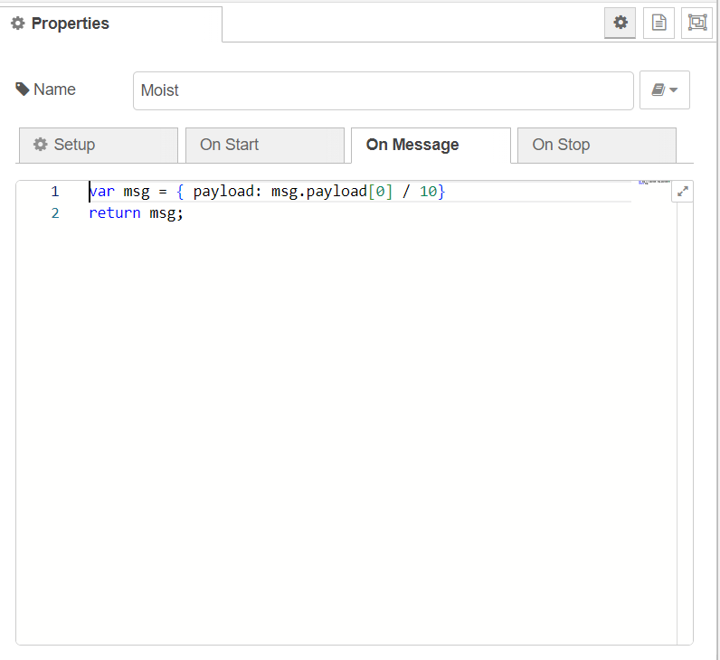
The code of the moist function.
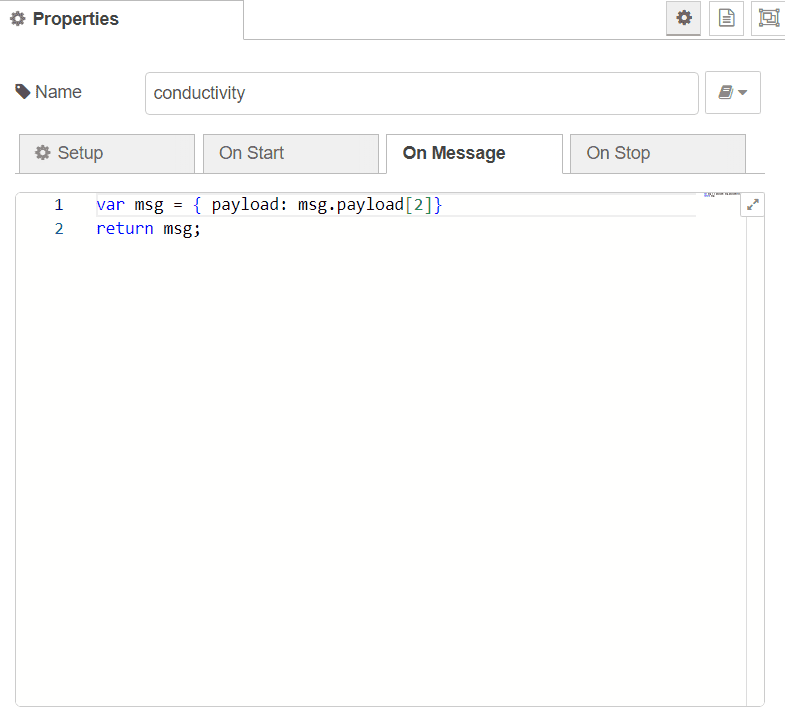
The code of the conductivity function.
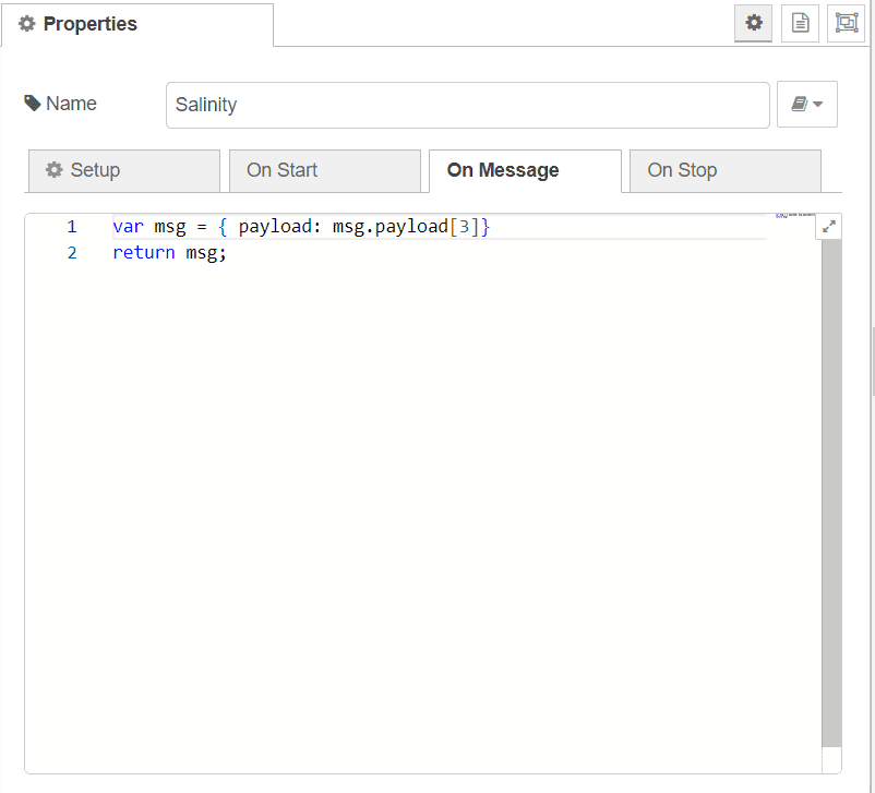
The code of the salinity function.
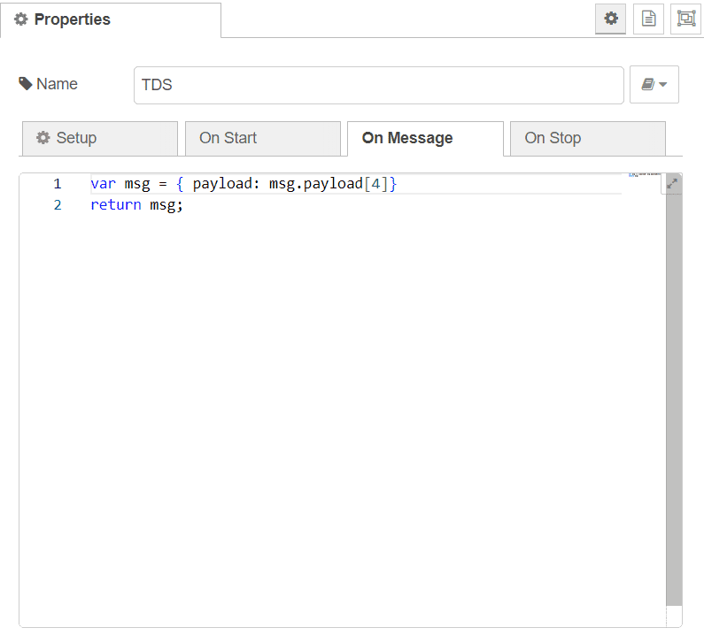
And the code of the TDS function.
Now drag a gauge, chart and a debug for each function.
Next, we will need another modbus node for the Humidity and temperature sensor, Drag another delay and Modbus Getter.
Name the node and set the Unit ID to 2, FC to FC3: Read Holding Register, address 0 Quantity 2.
Use the same server you used for the other sensor.

Add two function nodes, each with a chart , guage and a debug as the moist sensor.
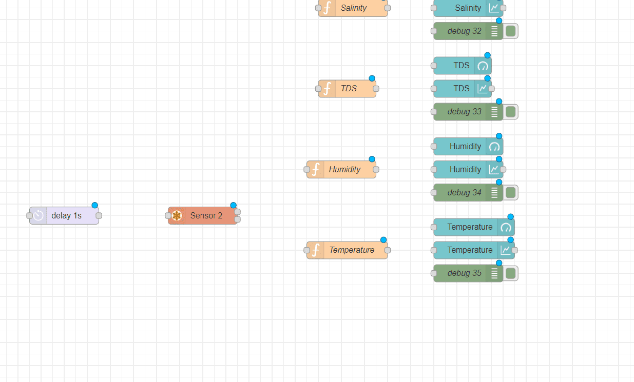
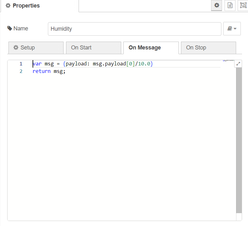
The code of the Humidity function.
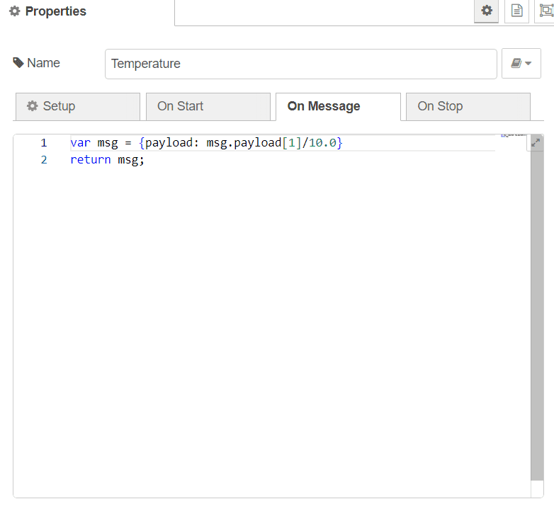
And lastly The code of the Temperature function.
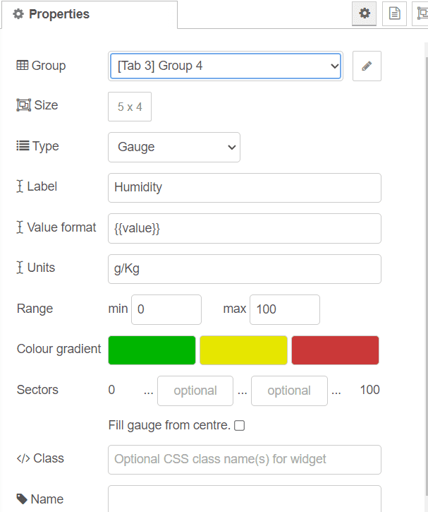
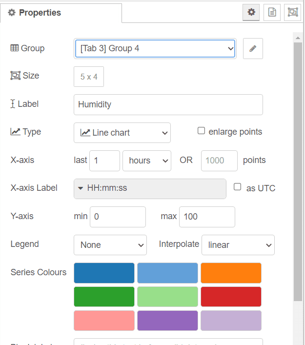
For each gauge; ensure that you add it to the 4th group. you can label it for your dashboard and style it if you wish.
Do the same for each chart you have add it to your flow, add them to group 4 and name them.
Connoect all the nodes of this group as show below.
And finally; you can go to your dashboard and start managing your system
An example of a dashboard shown in this image, you can improve your dashboard style by naming the tab and group, adjusting thems and colors and repositining the groups.

Congrats!! you completed your own IRIV Agriculture Box