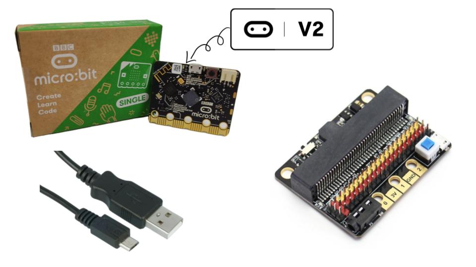
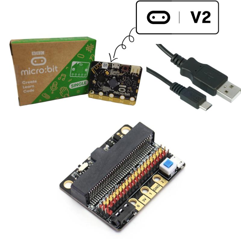
Note: There are three options of Kittenbot IOBit V2 to choose from:
- Kittenbot IOBit V2 Expansion Board WITH micro:bit V2 and a USB micro B cable
- Kittenbot IOBit V2 Expansion Board WITHOUT micro:bit board.
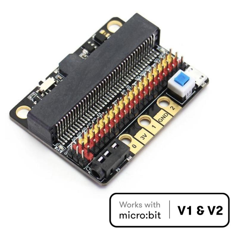
Note: This IOBit Expansion board works with both the micro:bit V1 and micro:bit V2.

This is a low-cost expansion board for micro:bit, which is specifically used for the IO ports of micro:bit. It has taken all the IO resources on the micro:bit, and also come with a built-in buzzer. The buzzer is connected to the P0 pin through the slide switch. The small size is very suitable for small projects using micro:bit.
Product parameters:
Length x width x height: 57mmx44mmx12mm
.jpg)
Technical parameters:
- Power supply mode: IObitV2.0 supports a USB5V power supply. This power supply mode requires pressing the blue power switch.
- Working voltage: 3V-5V (5V sensor module is not supported under 3V power supply)
- Output current: 3V and 5V power interface with maximum output 1A
- Serial port extraction: serial port can map IO port
.jpg)
- I2C port leads: pins 19 and 20 can only be used as I2C function pins. They cannot be read and written as ordinary IO ports, because micro:bit bottom is dead.
- SPI port leads; 14, 15 (IO port can be read and written).
Programming:
MakeCode/KittenBlock (based on Scratch3.0) with hardware: micro:bit.
Introduction to IObit hardware:
5V power
.jpg)
Insert the USB power supply (5V 1A) as shown in the above figure. Press the blue button at 2, and the red indicator light at 3 will light up. You can use the left 5V interface.
P0 buzzer
.jpg)
The slide switch to turn on or off the buzzer function (see the silkscreen on the back of the board for status)
3Pin IO port leads
All the pins in the micro:bit have been taken out without any reservation (Note: there are no P17 and P18 on the micro:bit, it’s not that the IObit is not taken out)
- Yellow corresponds to the different IO pins
- Red corresponds to 3.3V/5V (with silkscreen)
- Black corresponds to GND
5PIN gold fingers
- The gold fingers of the micro:bit are used to draw 3v, gnd, P1, P2, and P3 respectively. This is for users who prefer to use alligator clips
- 40P micro:bit horizontal socket
- Board mounting holes and fixing
- The two outermost holes are approximately 4.8 mm in diameter and are compatible with Lego friction pins with a spacing of 48mm.
- 3.5mm audio interface
- You can plug in a 3.5mm jack audio device and play the sound of the P0 pin.
IObit programming use:
If you haven’t gotten started with micro:bit, first get started with micro:bit, this is the operating premise.
Use music blocks directly in MakeCode to
.jpg)
If you use P0, remember to turn the buzzer toggle switch off (because the buzzer is combined with P0)
When using the micro:bit power supply, IObit IO port drive capability is very weak, IO port current is less than 200mA, please do not connect high current devices (such as large servo MG995, DC motor), otherwise, it will burn out the micro:bit, you must fully understand before using what the device current conditions needed
When using a 5V external power supply, you can drive multiple small servos, but please note that the maximum current is 1A!
If you use the high-low read function of the pin, you must set the pull-down on the pin.
.jpg)
If P0 is used as a normal IO port, the buzzer toggle switch must be turned off, otherwise, the buzzer will sound or the IO read value will be abnormal.
Use the shared pin with the micro:bit dot matrix (such as 3, 4, 5, 6, 7, 8, 9, 10, 11), remember to disable the dot matrix screen on the software, otherwise, it will be a bit of a screen burst
Do not use IO19, 20. 19 and 20 cannot be used as an IO port. Although the display on the MakeCode software can be used, it is not used! It can only be used for I2C communication
The USB port allows a maximum input current of 1A.
Do not place it on a metal surface to avoid short circuit
Warranty Period: 12 months
 International
 Singapore
 Malaysia
 Thailand
 Vietnam


.jpg)
.jpg)
.jpg)
.jpg)