 International
 Singapore
 Malaysia
 Thailand
 Vietnam
Your shopping cart is empty!
LCD: Interfacing with PIC Microcontrollers (Part 3) – Creating Custom Character
By SCLim
RH2T Magazine, Vol.6, Sep 2010
I guess many of us find working on the predefined characters of the LCD program are kind of boring after some time. Here I'll show you how to create your own custom characters.
Revision
General information on the LCD, circuit connection to the PIC microcontroller, software initialization, commands, instruction sets, and the basic sample program has been discussed in the previous issues. With all that, you can display anything you want on the LCD, but it has to be based on predefined characters. So this tutorial is drafted to show you how to make use of the CGRAM of the LCD to create your own characters or patterns. Hence you can display more interesting stuff on your LCD!
Character Generator Random-Access Memory (CGRAM)
All character-based LCD of type HD44780 has CGRAM. In order to create custom patterns, we need to store values to the CGRAM defining which pixel to glow. From the figure shown below, 6 bits address from DB0 to DB5 (ACG) is used to access 64 bytes of the CGRAM area.
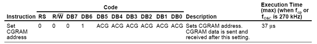
Figure: CGRAM command and address.
When you are using 5x8 dots LCD with 64 bytes of data space, you can define a total of 8 user defined patterns. Although one row is consisting of 5 pixels, one byte is needed for each row and 8 rows are needed to complete each pattern. When LCD is working in 5x10 dots, you can only create 4 user defined patterns. However, we will only discuss 5x8 dots LCD type in this article. The figure below shows the typical 5x8 dots LCD pixel map for a single character.
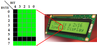
Figure: A typical 5x8 dots character pixel map showing 'L'.
CGRAM Address
The memory map of the 8 user defined characters is given in the table below. The first character will occupy 8 bytes, starting from 0x00, until 0x07. Then the next character starts at 0x08 and ended at 0x0F. This trend continues until the end of the CGRAM address, which is 0x3F.
Pattern | CGRAM Address (ACG) |
0 | 0x00 – 0x07 |
1 | 0x08 – 0x0F |
2 | 0x10 – 0x17 |
3 | 0x18 – 0x1F |
4 | 0x20 – 0x27 |
5 | 0x28 – 0x2F |
6 | 0x30 – 0x37 |
7 | 0x38 – 0x3F |
Table: CGRAM memory map.
By referring to the first figure (CGRAM command and address), since bit 6 (DB6) is always '1' and bit 7 (DB7) is always '0', we can point to certain CGRAM address by sending the sum of CGRAM address (ACG) and 0x40 (0b01000000). For example, we send the command as 0x48 (= 0x08 + 0x40) to point the cursor to the CGRAM address of pattern 1. In other words, although 0x08 is the actual CGRAM address, we need to send the code 0x48 to the LCD module to produce the correct result. Examples are given in the table below. You will notice that the hexadecimal codes are actually the sum of 0x40 and the CGRAM addresses in the previous table.
Pattern | Binary Code (0bxxxxxxxx) | Hexadecimal Code | |||||||
Fixed | CGRAM Address | ||||||||
DB7 | DB6 | DB5 | DB4 | DB3 | DB2 | DB1 | DB0 | ||
0 | 0 | 1 | 0 | 0 | 0 | 0 | 0 | 0 | 0x40 |
1 | 0 | 1 | 0 | 0 | 1 | 0 | 0 | 0 | 0x48 |
2 | 0 | 1 | 0 | 1 | 0 | 0 | 0 | 0 | 0x50 |
3 | 0 | 1 | 0 | 1 | 1 | 0 | 0 | 0 | 0x58 |
4 | 0 | 1 | 1 | 0 | 0 | 0 | 0 | 0 | 0x60 |
5 | 0 | 1 | 1 | 0 | 1 | 0 | 0 | 0 | 0x68 |
6 | 0 | 1 | 1 | 1 | 0 | 0 | 0 | 0 | 0x70 |
7 | 0 | 1 | 1 | 1 | 1 | 0 | 0 | 0 | 0x78 |
Table: Examples of the CGRAM address and the combined code.
Creating Custom Character
Let's take a look at how a custom character is defined. There are many free LCD character generator programs, such as LCD Express for AVR microcontroller designed by Vega-XP and the online Custom-Character Generator hosted by Scott Edwards Electronics Inc. Those programs are really helpful but I personally prefer to use the manual method. This is because most of the programs give you the hexadecimal value for each row of pixels, but the simplest way is to look into the binary value.
All we have to do is make a pixel-map of 5x8 and get the binary value for each row. A bit value is '1' if the pixel is glowing and the bit value is 0 if that pixel is off. I'll use a smiley J pattern to further explain it. The figure shows my version of smiley face. It may look less smooth due to the limited pixels available but I believe you can recognize the happy face with a pair of eyes and the raised mouth's corners.
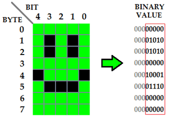
Figure: Smiley pattern with the corresponding binary value for each row.
The last row is usually left blank (0b00000000) for the cursor. If you are not using cursor, you can also make use of that row 7. This will give you more pixels for one pattern. Now we have the values for each row to create a smiley pattern. As you can see in the table below, the binary value can be used directly as the argument for LCD_senddata( ) function. We only need to add '0b' in front of each value to declare that it is a binary value.
Row | CGRAM data (binary value) | Argument x in lcd_senddata(x) |
0 | 00000000 | 0b00000000 |
1 | 00001010 | 0b00001010 |
2 | 00001010 | 0b00001010 |
3 | 00000000 | 0b00000000 |
4 | 00010001 |