 International
 Singapore
 Malaysia
 Thailand
 Vietnam
Your shopping cart is empty!
")
IRIV PiControl - Node-RED Modbus RTU - Multiple RS485 Sensors (Daisy Chained)
Previously we already learned the following:
- how to read temperature and humidity with Node-Red
- how to read voltage, current, and power in Node-Red
But what if you want to read both of them? Or even use more sensors? RS485 protocol is well-known for its capability to communicate with multiple devices through a daisy-chained connection method, using only one RS485 port. In this tutorial on using IRIV PiControl with Node-RED, we will learn how to communicate with multiple devices simultaneously, using the RS485 port on IRIV PiControl.
Hardware
- IRIV PiControl
- 24V DC Power Supply
- Industrial Grade RS485 Temperature & Humidity Sensor
- ADL200 Power Meter
Set Unit ID for the Sensors
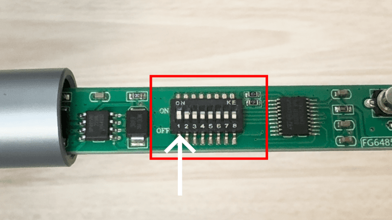
Previously we only used one sensor at a time. This time, we need to set different unit IDs for each sensor. First, let's set the unit ID on the temperature and humidity sensor. Gently open both ends of the sensor, one at a time. Carefully remove the PCB from the metal shell. You'll find the DIP switch on the PCB, which determines the Unit ID. For this tutorial, we'll set the Unit ID to 1. Refer to the datasheet for detailed instructions on setting the Unit ID.
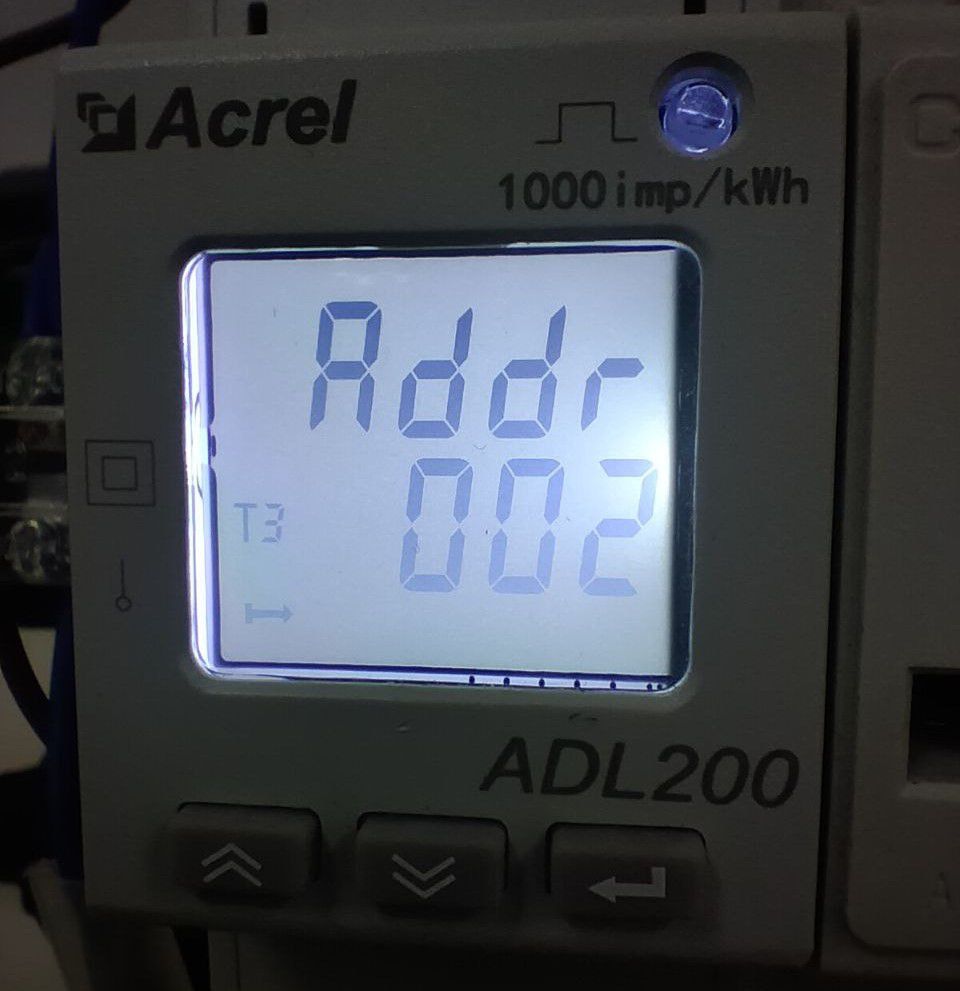
Next, set the unit ID for the ADL200 Power Meter to 2. You can easily set the unit ID using the buttons on the power meter. Please refer to the datasheet for detailed instructions on setting the Unit ID.
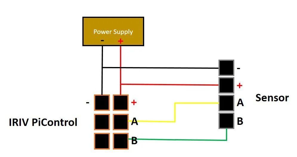
Connection Diagram
Power Supply Connection:
- Start by powering up the power supply using 120-240V AC source.
- Connect the power supply to the IRIV PiControl.
Temperature and Humidity Sensor Connection:
Since we're working with an isolated power connection system in IRIV, we will have to use the external power supply for the sensor.
- Connect the black wire to power supply GND
- Connect the red wire to power supply VIN
- Connect the yellow wire to (RS485 A) pin in IRIV
- Connect the white wire to (RS485 B) pin in IRIV
Note: Please remember to handle all connections with care and double-check connections for accuracy.
Power Meter Connection:
Since we're working with an isolated power connection system in IRIV, we will have to use the external power supply for the sensor.
- Connect port 21 on the power meter to (RS485 A) pin in IRIV
- Connect port 22 on the power meter to (RS485 B) pin in IRIV
- Connect the live wire to the L port on the power meter.
- Connect the neutral wire to the N port on the power meter.
- Connect the L' port on the power meter to the live port on your load socket.
- Connect the N' port on the power meter to the neutral port on your load socket.
- Connect the earth wire to your load socket if necessary.
Note: Please remember to handle all connections with care and double-check connections for accuracy.
Node-RED Programming
Make sure you run Node-Red on your terminal.
node-red start
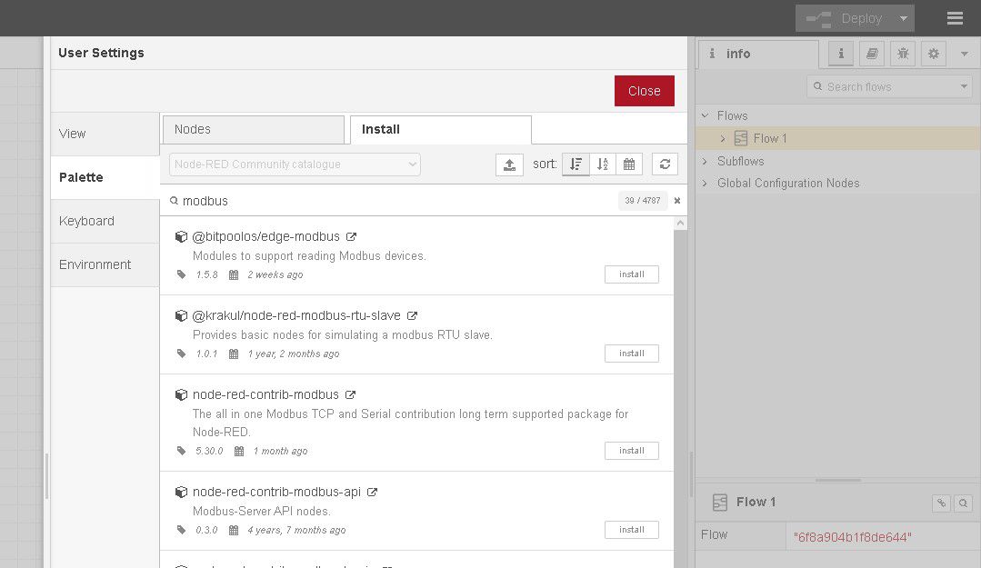
Next, we need to install Modbus nodes. You can do this using the Node-RED palette manager. Then, Look for these Modbus nodes (node-red-contrib-modbus).
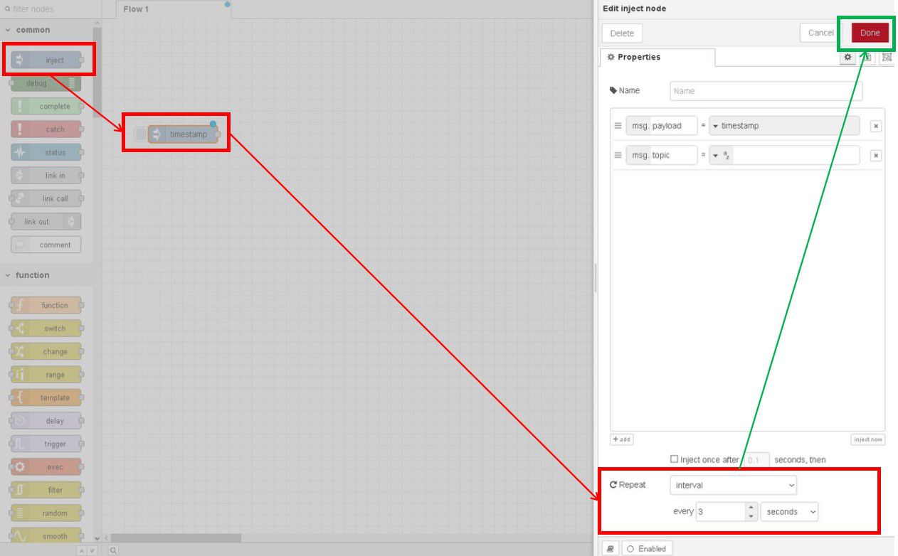
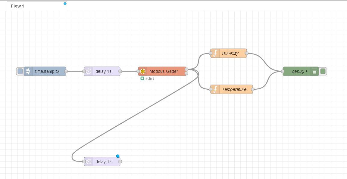
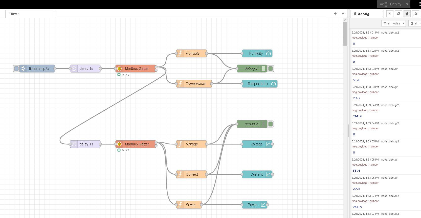
Let's start by dragging an inject node onto the flow. Open its properties and set (Repeat) to an interval of 3 seconds.
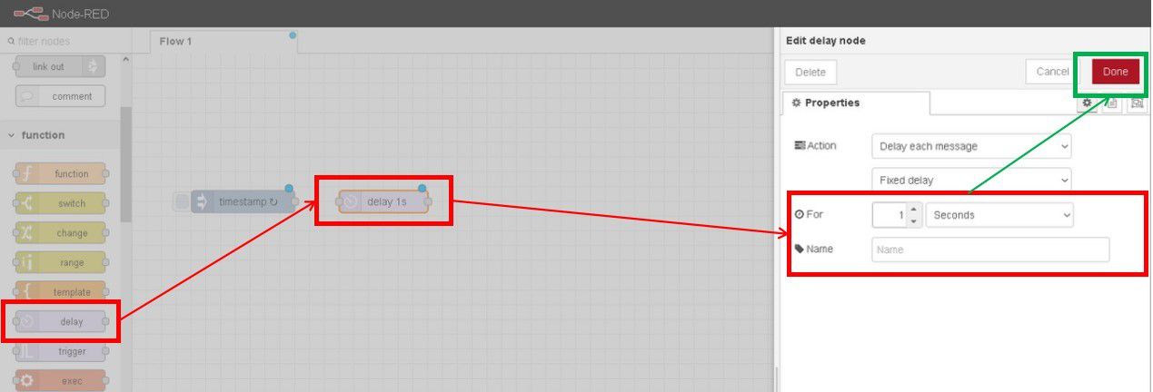
Because we want to read multiple RS485 readings, we are going to need to delay every reading, sequentially. If we trigger the multiple readings process at the same time, the reading will become unstable. Drag a delay node and set the delay for 1 second.
Next, drag and drop the Modbus Getter node and open its properties window.
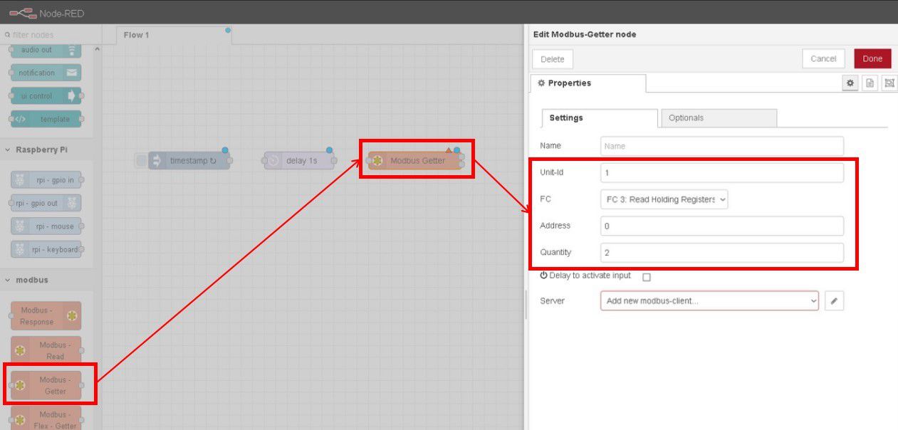
This Modbus Getter will read our first sensor, the Temperature and Humidity sensor. Adjust the following settings:
- Unit-Id: 1
- FC: FC 3: Read Holding Registers
- Address: 0 (The address of the register that stores Temperature readings)
- Quantity: 2 (The number of registers that we want to read consecutively, in our case, register 0 and 1, so a total of 2 registers)
Next, we have to edit the server settings.
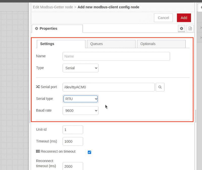
- Server Type: Serial.
- Serial Port: /dev/tty/ACM0 (default for IRIV PiControl RS485 Port)
- Serial Type: RTU
Click on Add, then close the window.
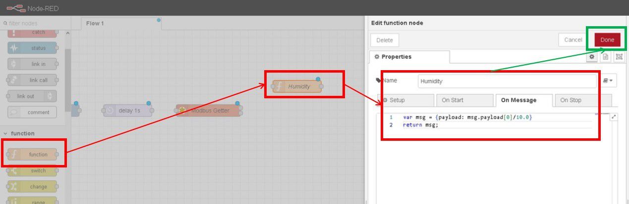
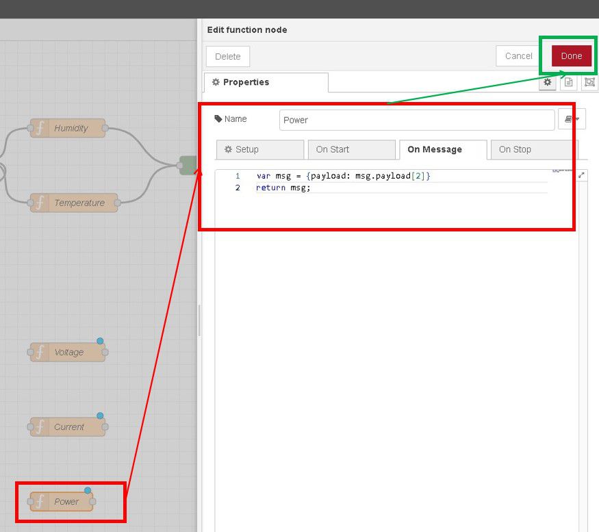
Now, drag a function node to get the humidity readings, open its properties, and write this short code. Number 0 in this line is to get the humidity register reading from the Modbus Getter node. Click done.
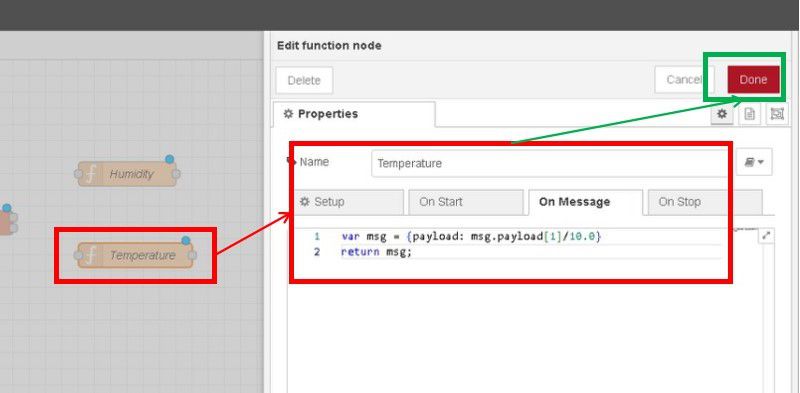
Drag another function node to get the temperature readings, open its properties, and write this code, make sure to adjust this number to 1, to get the temperature register readings.
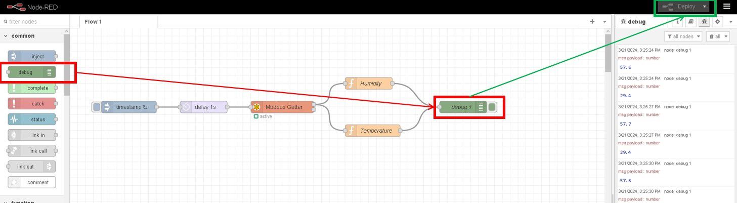
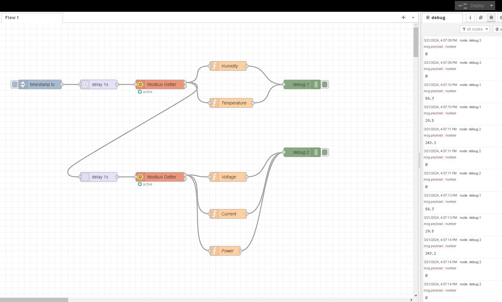
Now, drag a debug node to display the readings in the debug window. Connect all the nodes and click Deploy. The readings of the Temperature and Humidity sensor will appear.
Next, let's proceed with the Power Meter readings. Drag a second delay node onto the flow, and set it to 1 second. Connect it to the first Modbus Getter node. This will make sure that the readings for the power meter will only trigger when the Temperature and Humidity sensor has successfully obtained readings.
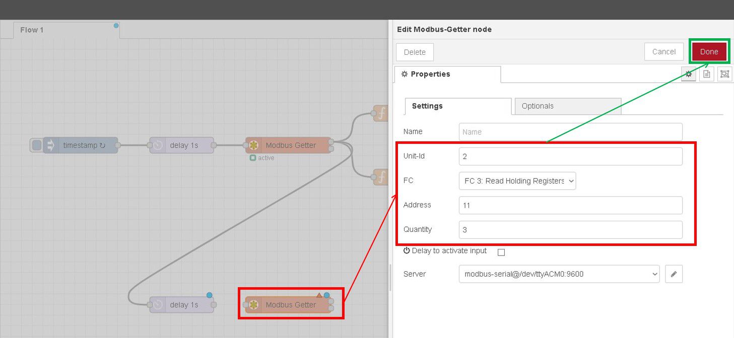
Drage the second Modbus Getter node. Use the server as before. Change the settings:
- Unit-Id: 2
- Address: 11 (The address of the register that stores Voltage readings)
- Quantity: 3 (The number of registers that we want to read consecutively, in our case, registers 11, 12, and 13 (Voltage, Current, and Power), so a total of 2 registers)
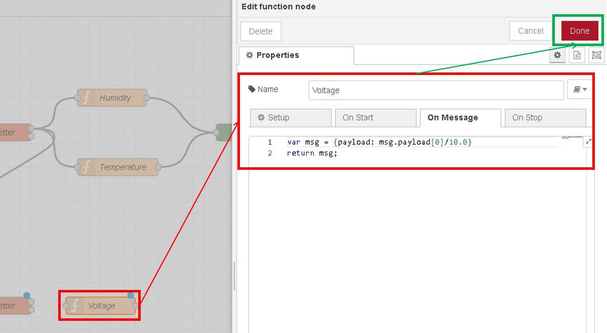
Next, drag a function node and write a short code to read the voltage.
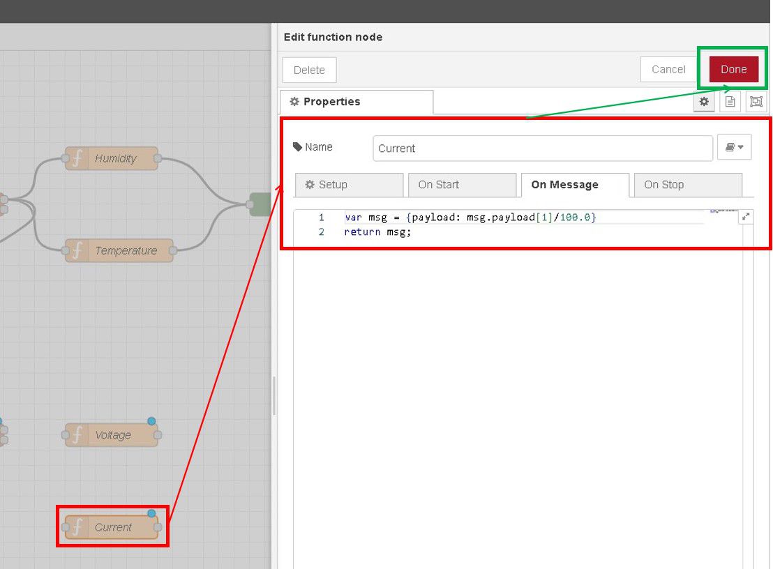
Next, drag another function node and write a short code to read the current.
Lastly, drag another function node and write a short code to read the power.
Now, drag a debug node to display the readings in the debug window. Connect all the nodes and click Deploy. You should notice the readings of the Power Meter will appear alongside the readings from the Temperature and Humidity sensor.
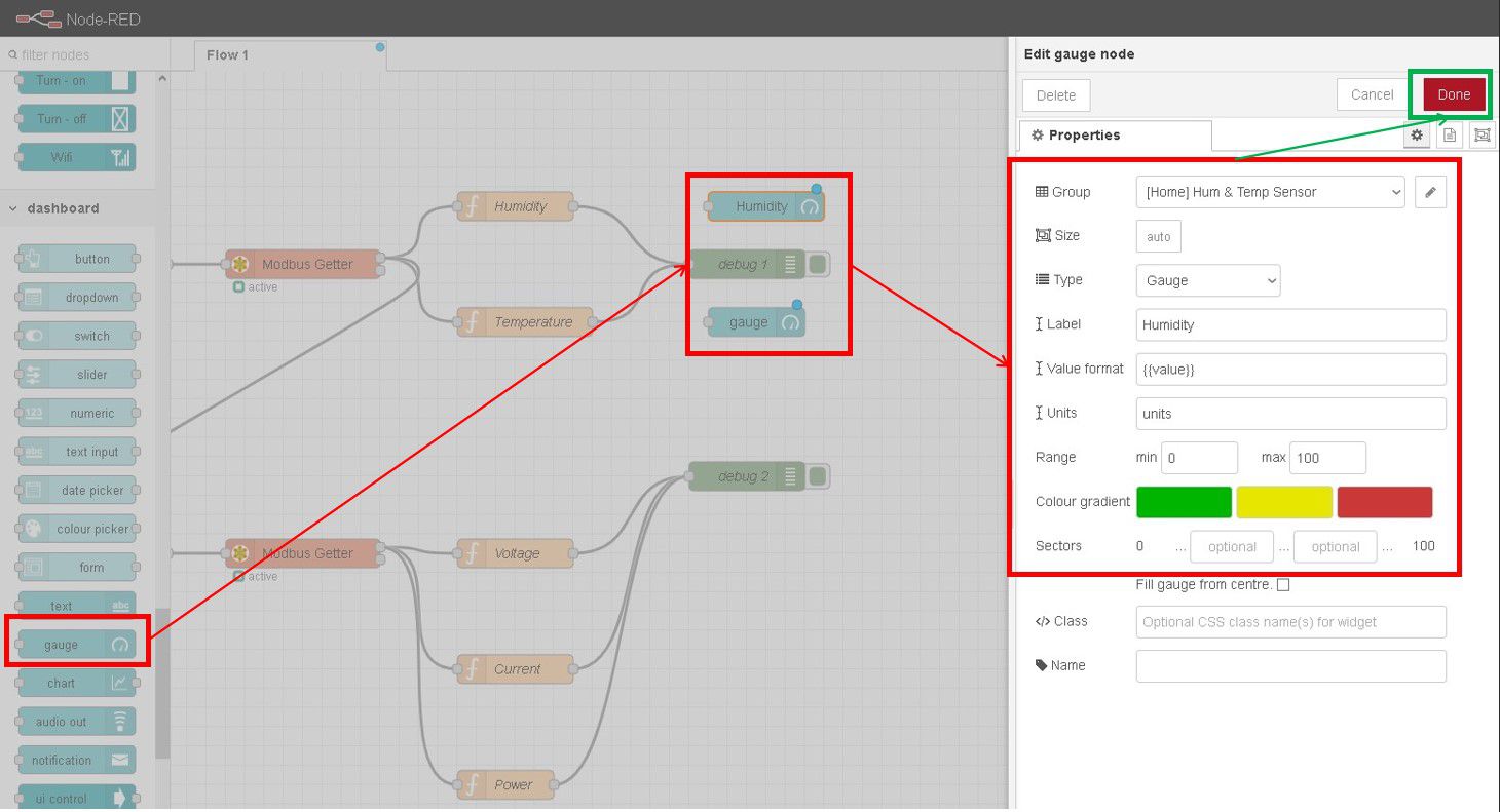
Next, let's add Dashboard nodes. Drag two gauge nodes and connect them to the Humidity and Temperature function nodes. Adjust the parameters and settings such as Value, Units, and Range to suit your measurements.
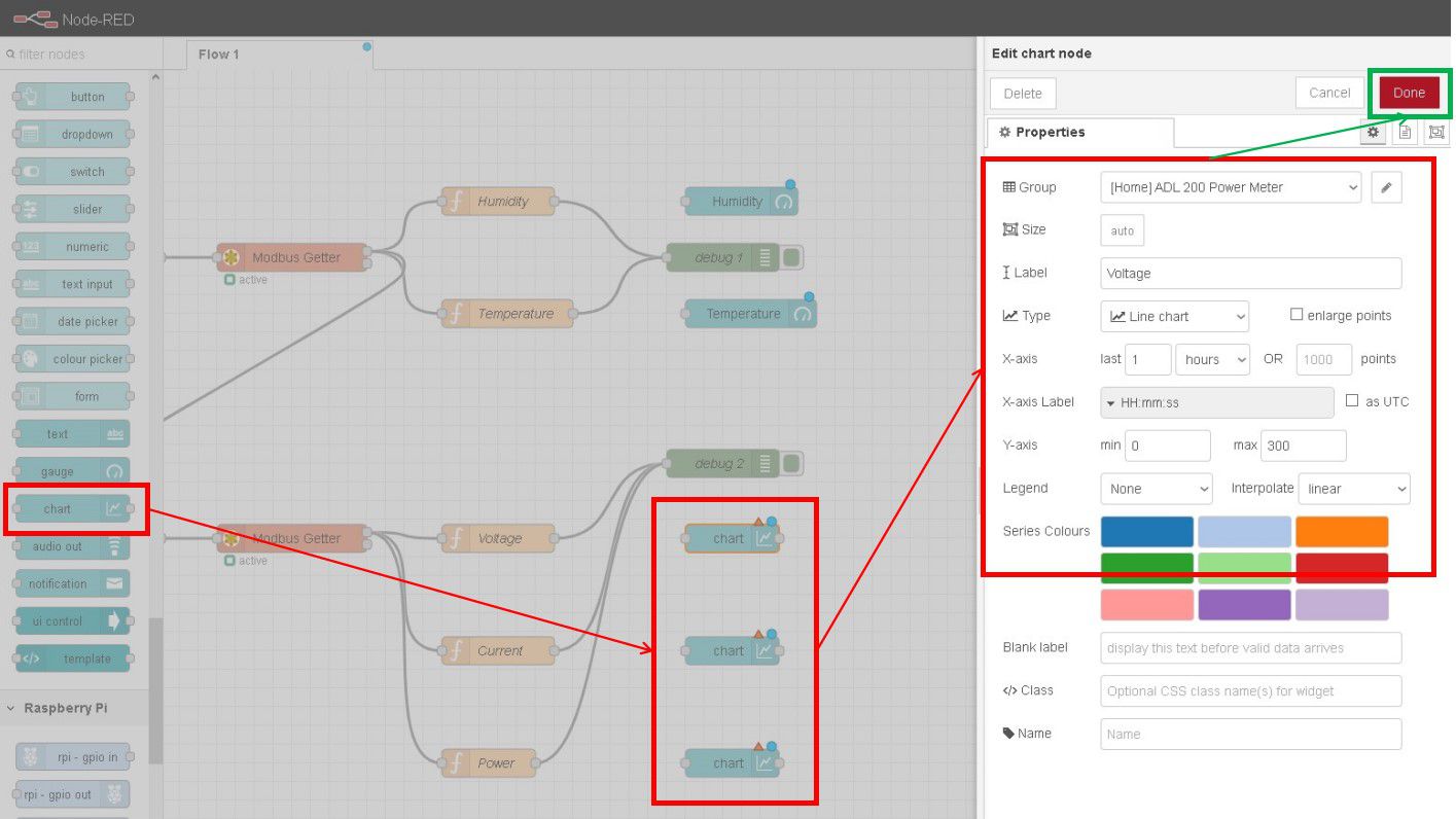
Next, drag two chart nodes and connect them to the Voltage, Current, and Power function nodes. Adjust the parameters and settings such as Value, and Y-axis to suit your measurements.
Connect the nodes properly and click Deploy.
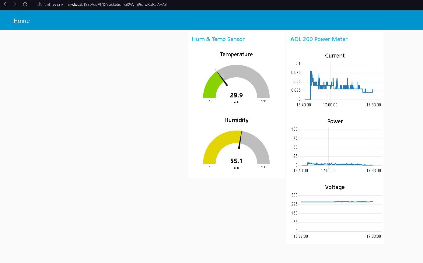
Now we are done. We can visit our Dashboard at this address:
iriv.local:1880/uiConnect some electrical load to see the Current and Power moves. Change the Y-Axis limit if your reading changes are too small.
That’s all for this tutorial, and stay tuned for more!