 International
 Singapore
 Malaysia
 Thailand
 Vietnam
Your shopping cart is empty!

Part 2: Digital Input with Cytron IRIV PiControl and CODESYS
- Huck Phin Ch’ng
- 29 Jul 2024
- Tutorial
- 138
This is a sample output of what we will achieve at the end of this section - the ability to toggle Cytron IRIV PiControl's LED0 on and off from a button press, programmed with CODESYS
Introduction
In the previous part, we have seen how to get started with Cytron IRIV PiControl and CODESYS. Now we would like to see how to add a digital input to the device and monitor its status through the visualization features in CODESYS.
What is "Digital Input"?
Digital inputs are used to monitor the on/off or high/low state of external devices or sensors, such as pushbuttons, limit switches, proximity sensors, or other similar devices. These inputs are typically wired to the PLC's input modules, which convert the electrical signals from the external device into a digital signal that the PLC can process. The PLC consists of multiple input channels, each corresponding to an individual input point. Each channel is connected to a specific digital input terminal on the PLC. The module provides isolation and protection for the PLC's internal circuitry.
When the external device associated with a digital input is activated (e.g. a switch is pressed, a sensor detects an object, etc.) the digital input module sends a corresponding signal to the PLC's central processing unit (CPU). The CPU then processes this input information and executes the programmed logic based on the detected states. In PLC programming, digital inputs are typically used as triggers or conditions for various control functions and decision-making processes. For example, a digital input may be used to start or stop a motor, activate an alarm, control a valve, or initiate a specific sequence of operations.
It is important to note that digital inputs are binary, meaning they can only detect two states: ON (high) or OFF (low). They are not suitable for continuous varying analog signals, which require analog input modules for accurate measurement and processing.
That's a brief introduction to digital input. Now let's look at the hardware that will be needed.
Hardware
To complete this part of the tutorial, we will need the following hardware:
Cytron IRIV PiControl
24V DC power supply
Momentary push button
22AWG Hook Up Wire
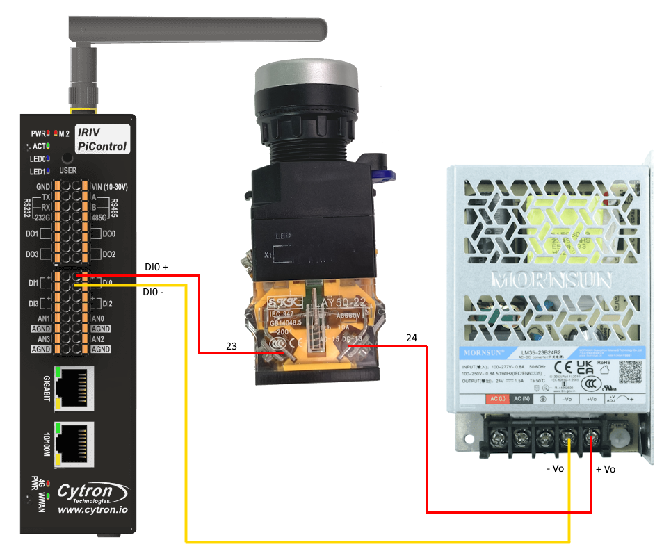
The wiring connection between the hardware pieces is shown in the figure below
Software
Open CODESYS and open the IRIV Codesys Tutorial project first created during the Simple LED Toggle With Cytron IRIV PiControl part.
Double click the PLC_PRG(PRG)
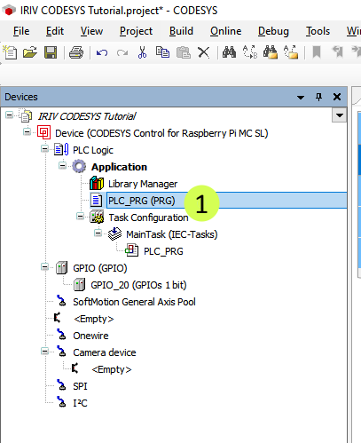
This opens the window for structured text programming
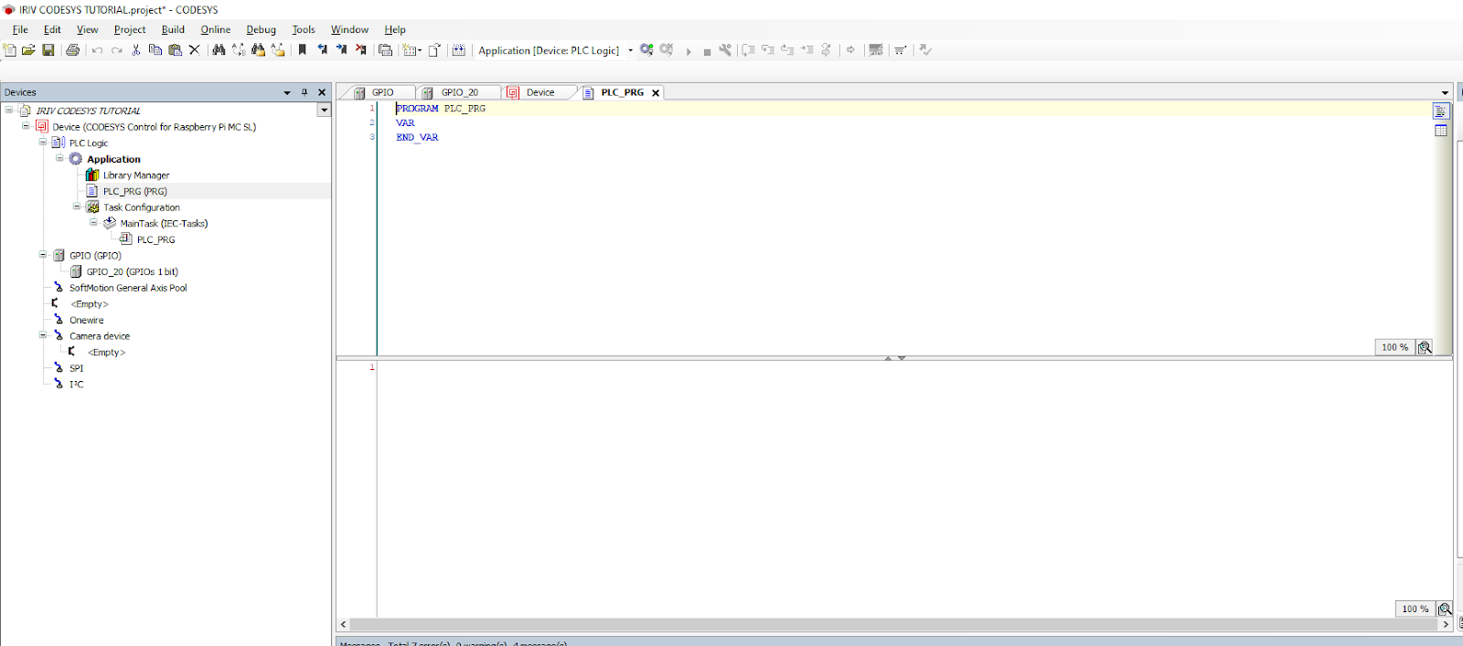
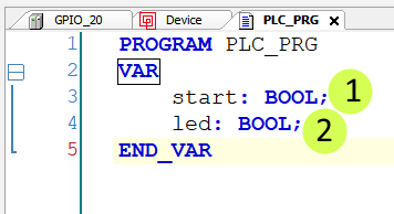
Type in 2 lines of variable declaration in line 3 and line 4
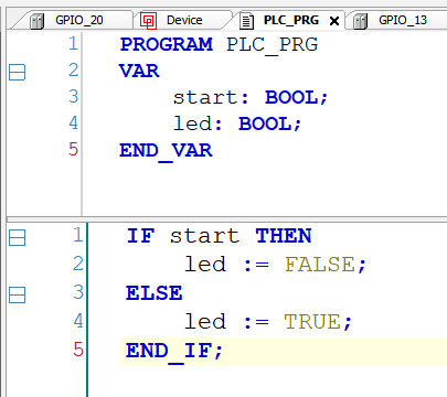
In the separate logic implementation section, type in an if statement as shown in the following image
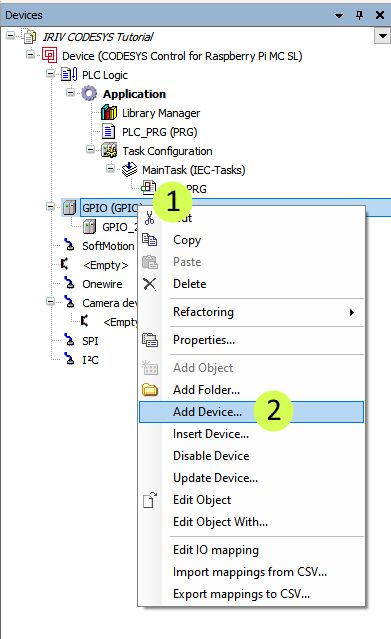
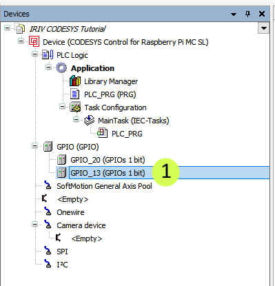
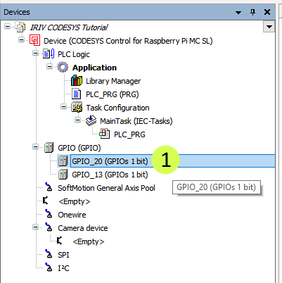
Right-click on the GPIO and choose Add Device.
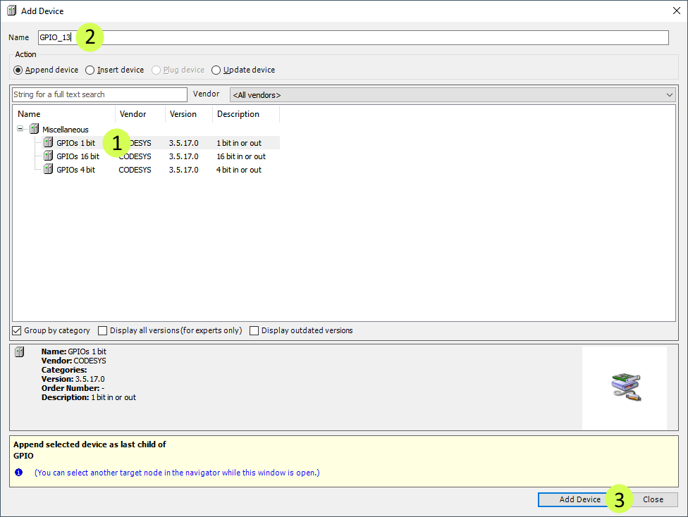
Choose GPIOs 1 Bit, enter GPIO_13 for the Name, and click Add Device.
Referring to the IRIV PiControl Datasheet, the Digital Input 0 port is mapped to GPIO 13.
Double-click on the GPIO_13 to bring up the configuration window
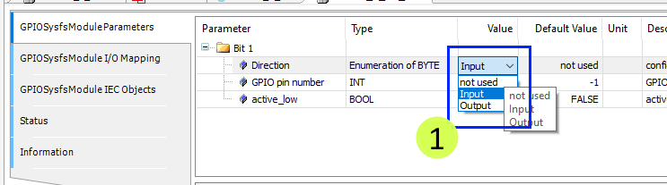
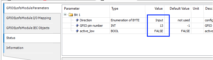
In the GPIO_13 configuration window, select the first tab "GPIOSysfsModuleParameters" to configure and assign the GPIO Direction, GPIO Pin Number, and current PIN state.
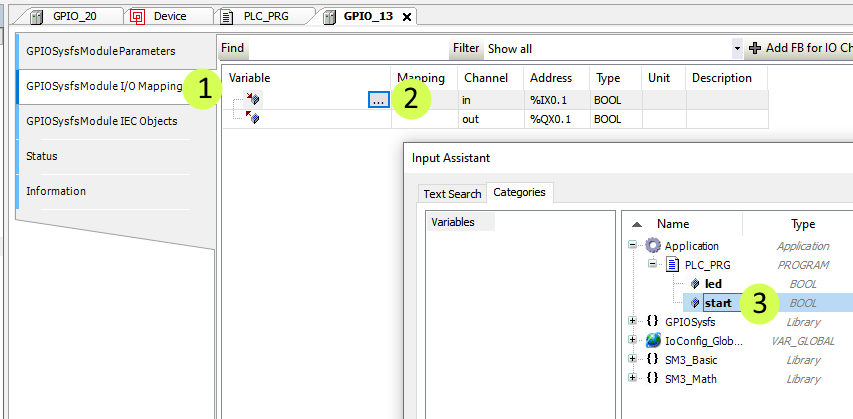
Next, go to the GPIOSysfsModule I/O Mapping and assign the start variable accordingly (refer to figure below)
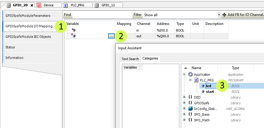
Double-click on the GPIO_20 to bring up its configuration window
Next, go to the GPIOSysfsModule I/O Mapping and assign the led variable accordingly (refer to figure below)
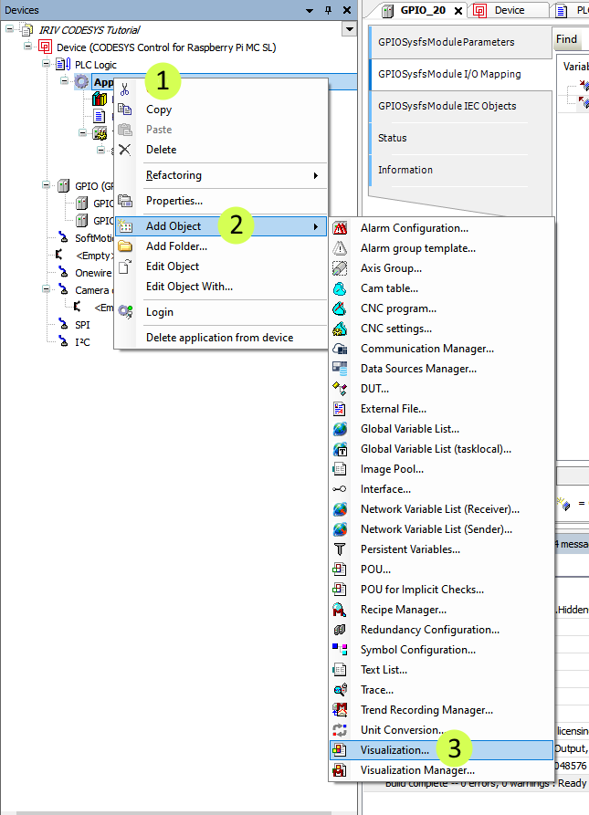
Once we are done with configuring the GPIO, we can now set up the visualisation. Right-click on the Application, click Add Object and choose Visualisation…
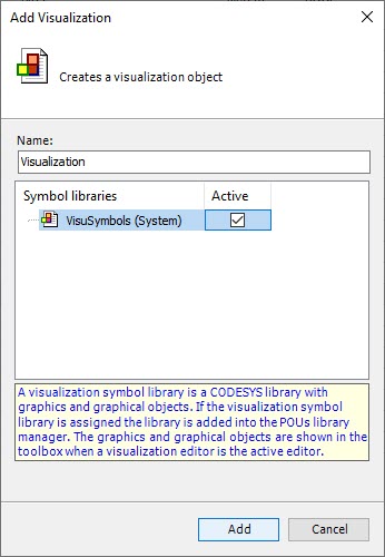
When a window pops up, tick the active and click Add.
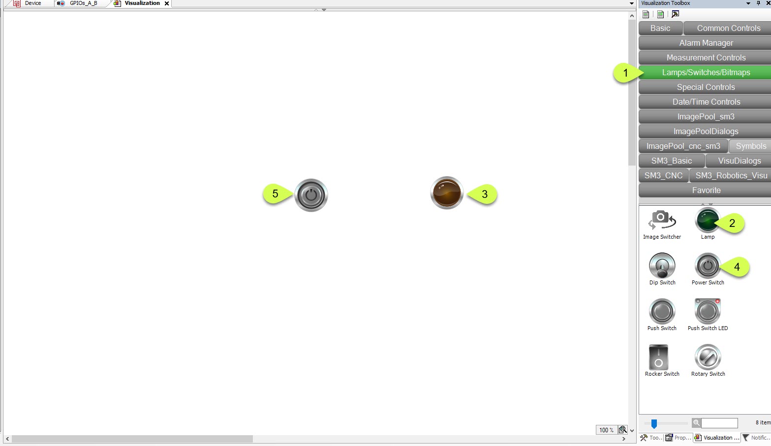
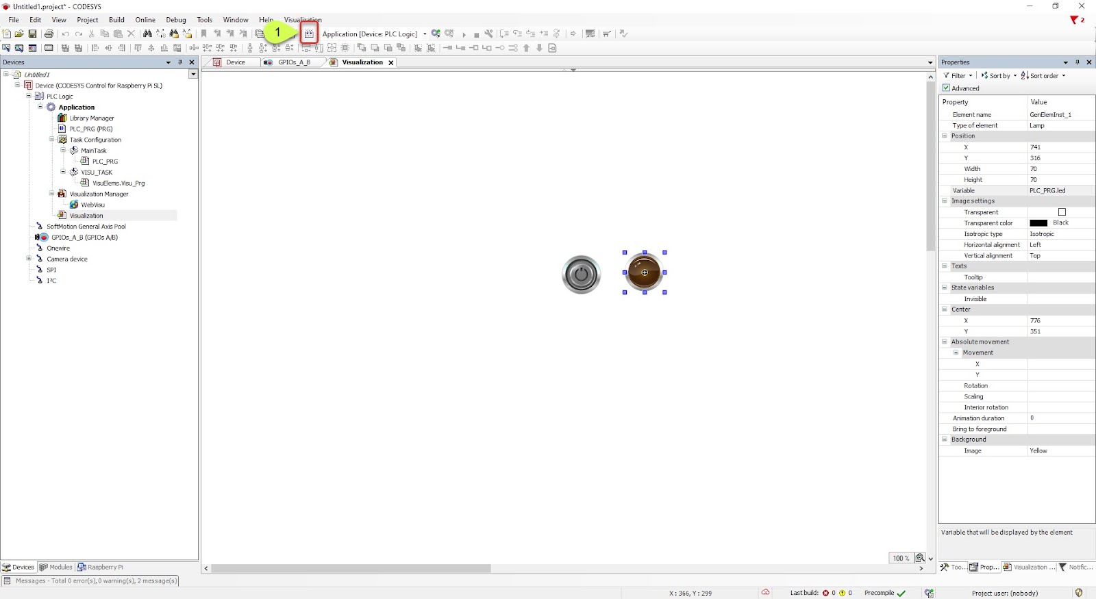
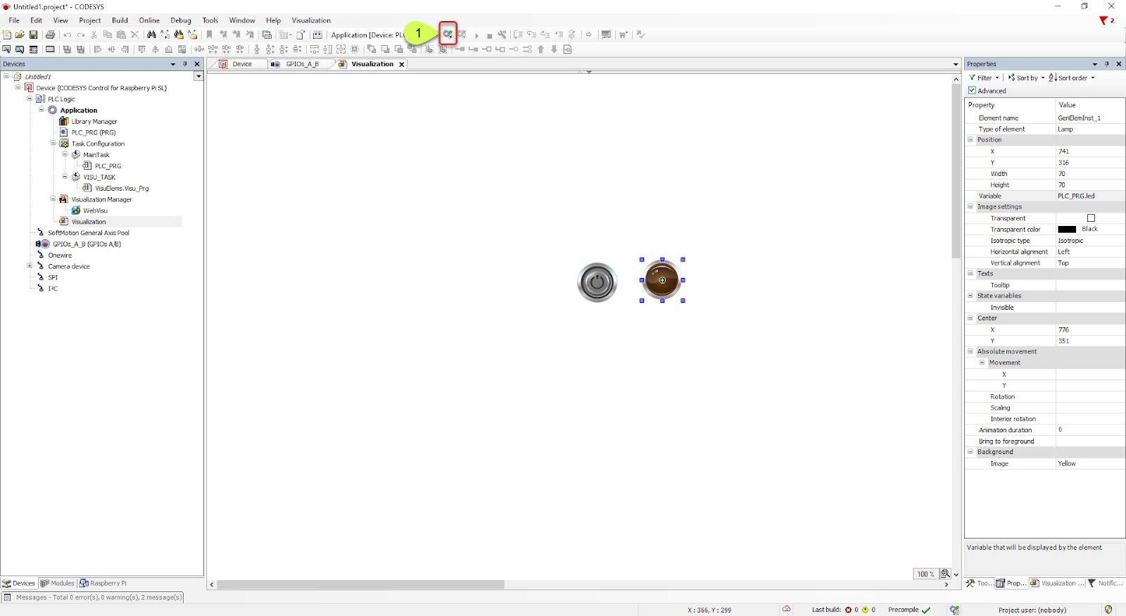
A visualisation window will appear. Choose Lamps/Switches/Bitmaps. First, choose Lamps/Switches/Bitmaps and draw a lamp and a power switch from the right to the centre.
NOTE: If you don’t see the items below the categories, click on the small up arrow below the categories.
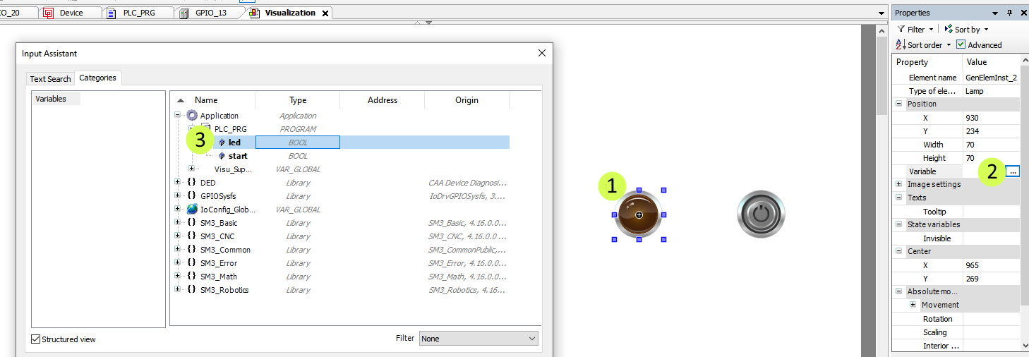
Now we want to configure the lamp. Click on the lamp, then select the three dots next to Variable in the properties pane. Expand the application, expand PLC_PRG, and select LED. Click OK.
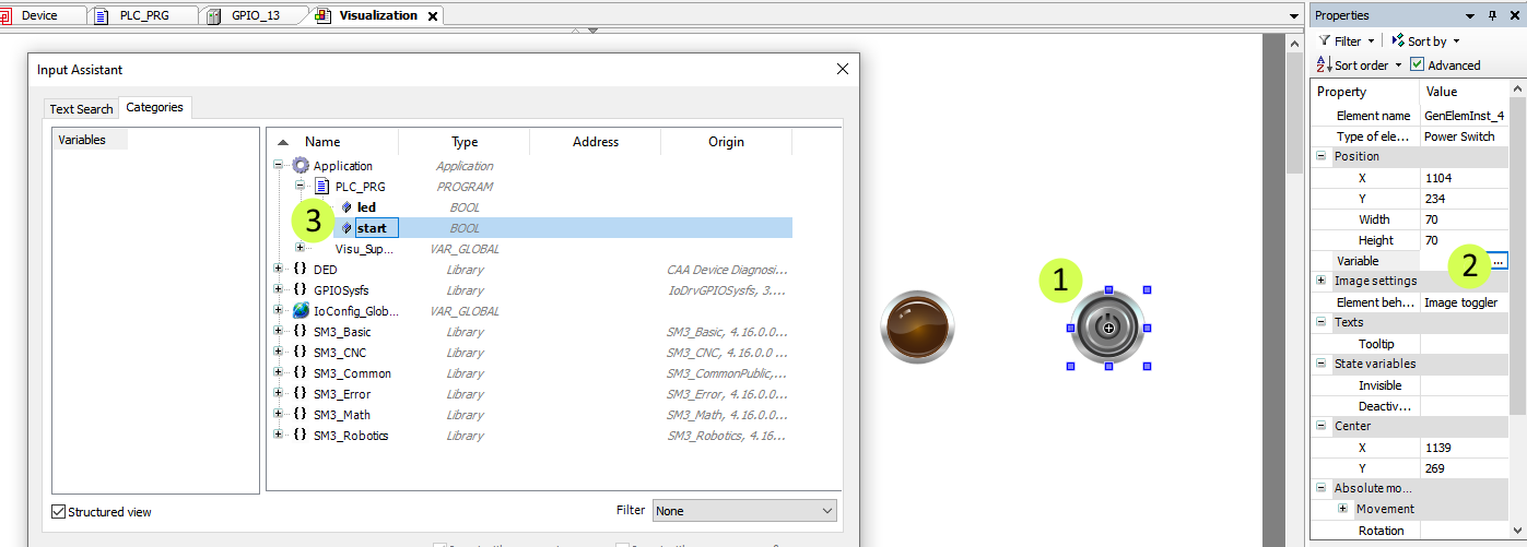
Now we want to configure the power switch. Click on the power switch, then select the three dots next to Variable in the properties pane. Expand the application, expand PLC_PRG, and select start. Click OK.
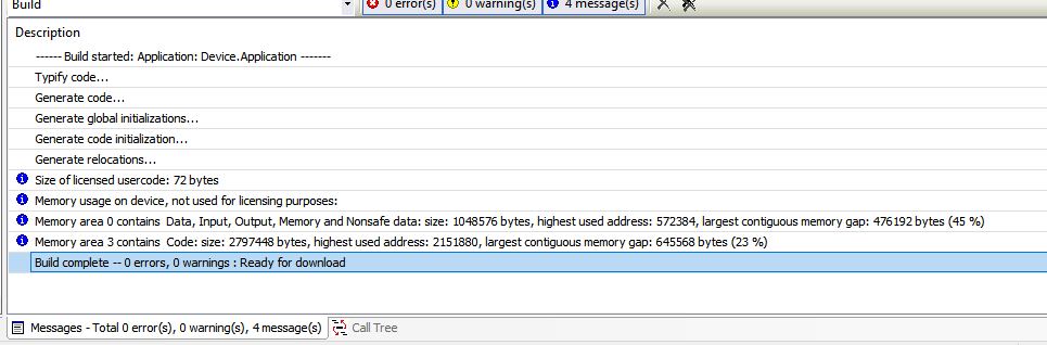
Click the Generate Code button
When you see the message Build complete - 0 errors, 0warnings: Ready for download, the Generate Code step was successful
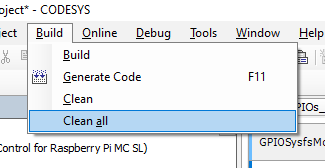
NOTE: If you encounter compilation errors like Cannot Convert Type, you can first try to go to the Build menu from the top toolbar and then click Clean all. Then acknowledge the popup window by clicking Yes.
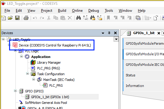
Next we want to login into the IRIV PiControl to online mode. First we need to double click the "Device (CODESYS Control for Raspberry Pi…)".
The device configuration window will open.
In the communication settings window, click on Scan Network
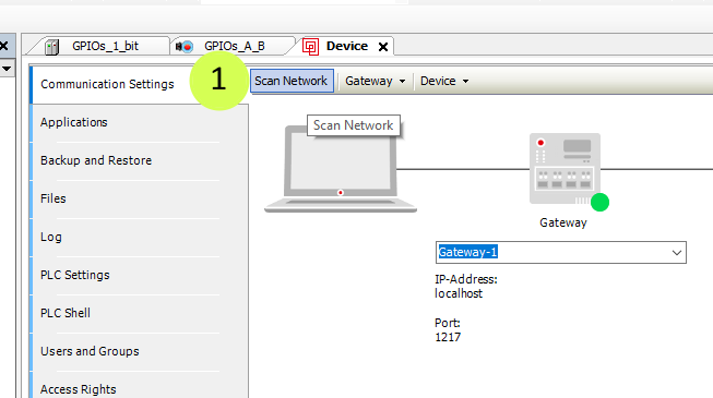
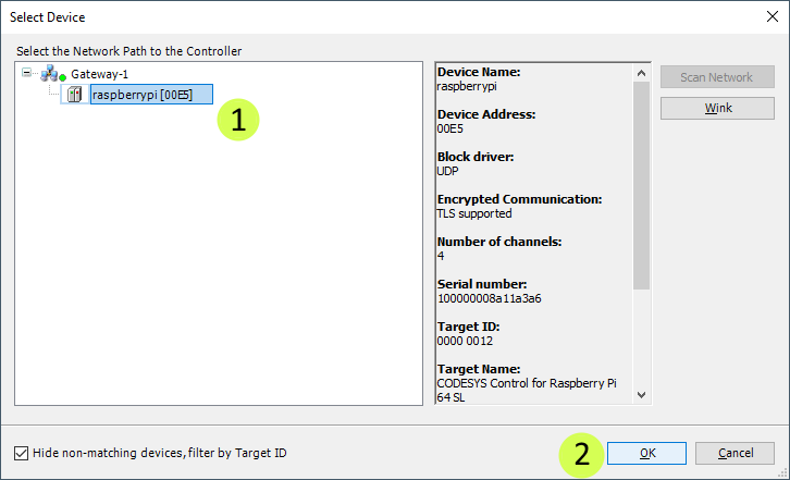
First, select IRIV PiControl under “Gateway” and then click Ok
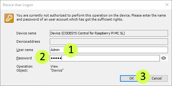
Type in "Admin" for the Name and "admin" for the Password. Then click OK.
NOTE: If you used custom particulars for the name, password, and confirm password earlier, use your custom particular instead.
Next, click the login button
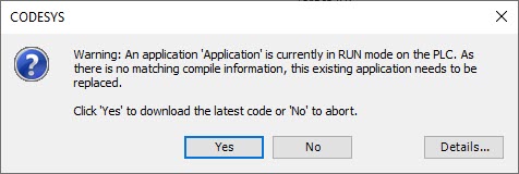
When this window pops up. Click Yes
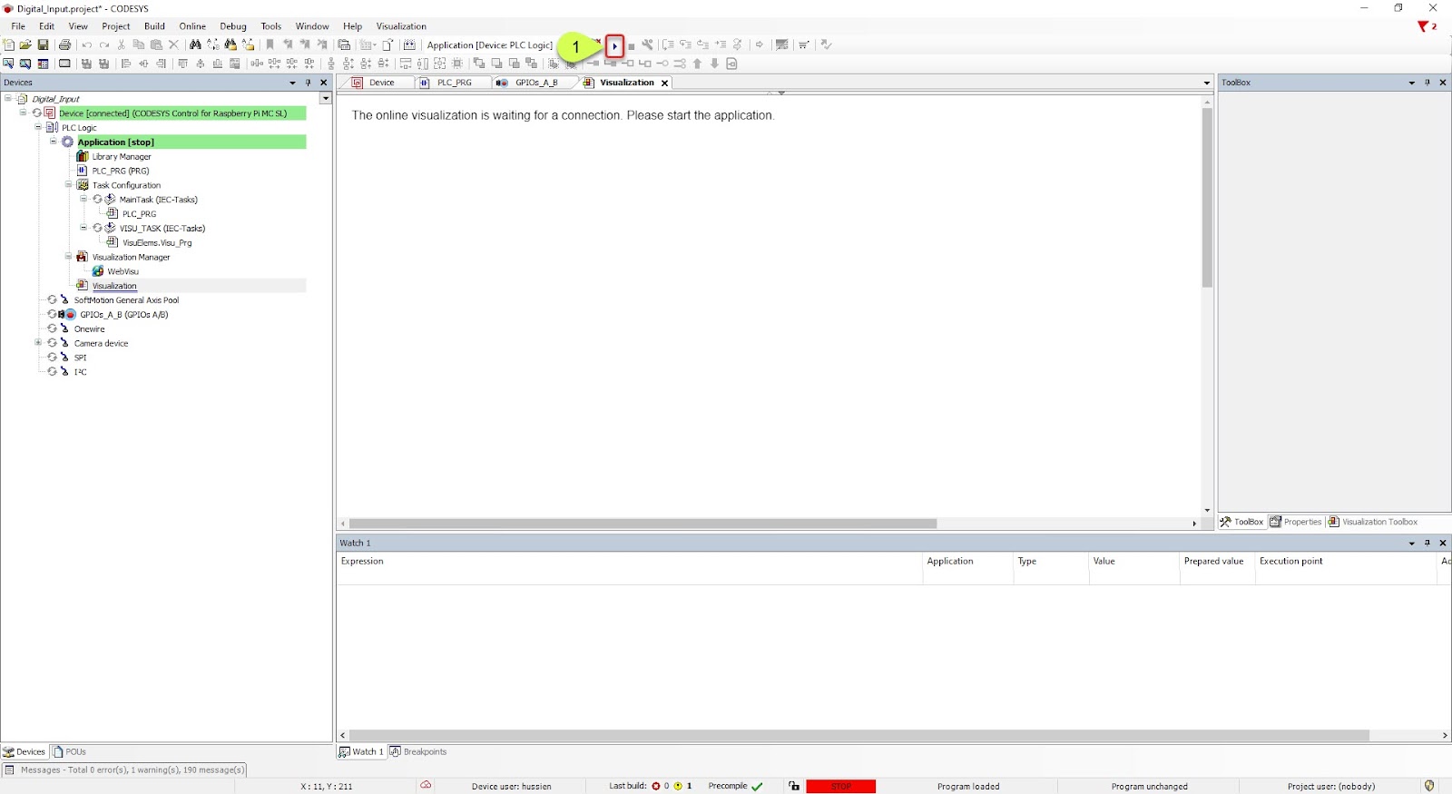
Click the Play button.
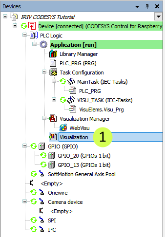
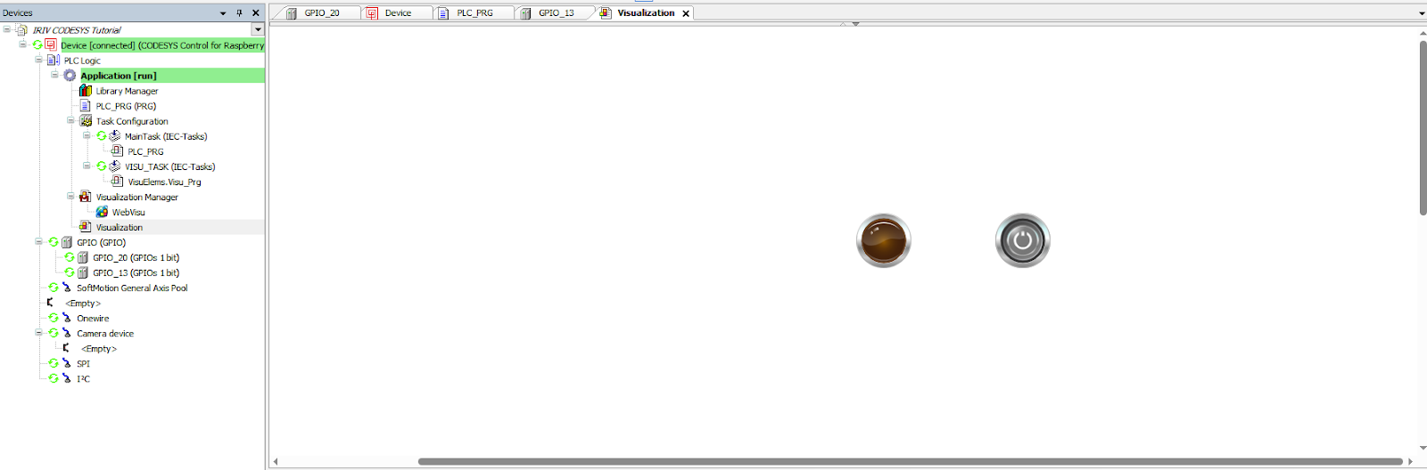
Double click on Visualization from the leftmost pane to return to the visualization
Now it's ready. When the momentary push button is pressed, the LED0 on IRIV will turn on.
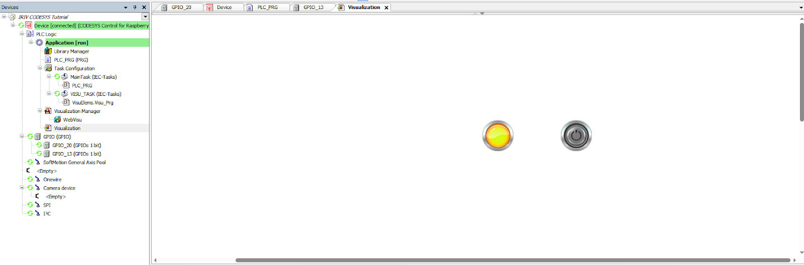
When the momentary push button is not pressed, the LED0 on IRIV will not turn on.
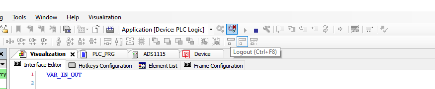
Before ending, click the tool button highlighted in the figure below (Logout) to safely logout.
Hardware Components

IRIV PiControl - IR4.0 CM4 Industrial Controller
RM1,345.00++
x 1 unit(s)