Your shopping cart is empty!
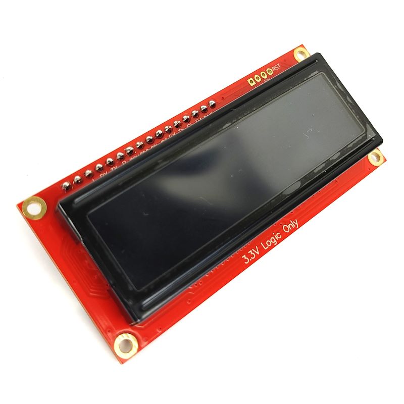
SparkFun 16x2 3.3V SerLCD - RGB on Black
- Brands Sparkfun Code: DS-SERLCD-3V3-B
Note: From 14 Sept 2021 onwards, the SerLCD is updated to the latest version.
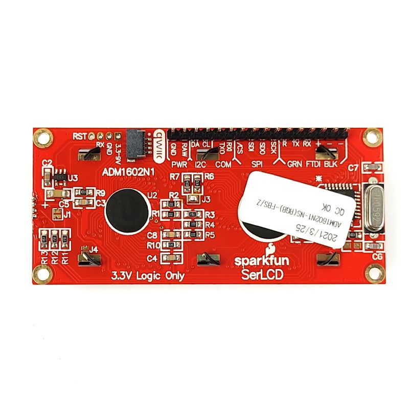
The latest versions of these LCDs have a Qwiic connector. The previous versions did not. Some of the pictures in this tutorial are from the previous version of the hardware. However, because the change is rather minor, they are still relevant. The pinouts along the edge are still in the same order and position (except for the left-most cluster of 4 PTH pins).

All Qwiic compatible products operate their I2C on the cable at a logic level of 3.3V, and so no conversion is necessary.
The SparkFun SerLCD is an AVR-based, serial-enabled LCD that provides a simple and cost-effective solution for adding a 16x2 RGB on Black Liquid Crystal Display into your project. We've seriously overhauled the PCB design on the back of the screen by including an ATmega328P that handles all of the screen control, meaning a backpack is no longer needed! This display can now communicate in three different ways: serial, I2C, and SPI. This simplifies the number of wires needed and allows your project to display all kinds of text and numbers.


Note: To make it easier for you, this Serial LCD comes with pre-soldered headers.
The on-board ATmega328P AVR microcontroller utilizes 11.0592 MHz crystal for greater communication accuracy with adjustable baud rates of 1200 through 1000000 but is default set at 9600. The firmware for this SerLCD is fully open-source and allows for any customizations you may need.
Note: Since the SerLCD is a 3.3V device, please make sure you convert to 3.3V logic depending on your chosen microcontroller or single-board computer. Otherwise, you may risk damaging the LCD.
This 16x2 SerLCD has a row of headers along the top side. This is where you can connect the power and your choice of communication protocol (Serial UART, I2C, or SPI). It also has 6-pin Arduino Serial port available for convenient firmware updates.

Note: If you choose Serial UART, there is a handy 3-pin JST footprint. This includes the minimum connections needed: RX, GND, and VIN. Our JST Jumper 3 Wire Assembly is a good way to go:
 |  |
This screen can be powered by 3.3-9VDC. You have two-pin options for connecting up power. One is labeled "RAW" and the other (on the 3-pin JST) is labeled "3.3-9V".
Note: The pin labeled "+" is NOT a power input pin! This is connected to the VCC of the ATmega329P (3.3V).

Note: If you plan to run 100% brightness on all three colors (red, green, blue), then it would be best to keep your power input voltage low. As close to 3.3V as possible is best. This will keep the onboard linear 3.3V voltage regulator nice and cool. It can accept up to 9V and power all three backlights at 100%, but it will get a little warm, and over years of use, potentially damage the Vreg. For more information about Vreg and why they heat up sometimes, please check out this tutorial: Power and Thermal Dissipation